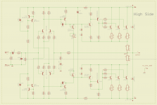
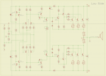
Just to make sure, I am re-posting the latest design of that elektor based grounded bridge.
This is the simple, no protection design for which I designed the pcbs as 2 separate boards for a prototype to resolve whatever issues it may have.
This is the simple, no protection design for which I designed the pcbs as 2 separate boards for a prototype to resolve whatever issues it may have.
Attachments
There is a good 200W 2N3055 grounded-bridge design in a 1981 issue (two months running) of Wireless World Magazine, with short-circuit protection too.
Very interesting. I poked around looking for this and I think I found what you're referring to. But it's not 1981, it was late 1980, in 2 issues, of september and october.
This will make an interesting read. At the time they didn't call it a grounded bridge, they called it a floating bridge, which is kind of the same.
And I'm not seeing anything about protections. Just a bare amp. They show how the low side can be simpler and of lesser quality compared to the high side, and the concept allows for lower distortions compared to traditional topologies.
They make use of some transistors that are no longer around, but the 3055 are and still manufactured. Some substitutions can be searched for and this could be an other project to work on.
It also shows how to do a bridged-bridge, for the real power maniac (Crown did a 10KW design around the 2N3773).
They are the masters for that concept for sure.
The 3773 isn't too different from the 3055, it's mostly the much higher Vce and max power dissipation setting them apart. The 3773 could quite easily be used instead of the 3055 in most circuits and the voltages be bumped up quite a bit.
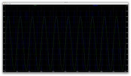
While trying to dig out my latest data for the grounded bridge amps, I found a simulation that I did for a complementary 2N3055/MJ2955 amp with an output stage topology based on bryston's.
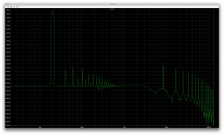
I can't recall if I shared all this, but the simulation was running great and as I am trying to remember how to use it and run the various sims, I had to re-learn certain things, including how to get FFT plots done.
I ran that sim again and took a couple of snapshots that I'm attaching here.
Does this look good?
I think it does, but I'd be curious to get impressions from others.
That amp is fully symetric and has 4 pairs of the 3055/2955. It has protections and runs on 35V rails. I made another such sim with MJ15015/16 substituted for the 3055/2955 with the rails bumped to 55V, and it's just as clean and runs great.
btw: that 3055/2955 sim ran with a 4ohm load. Not a bridge, just a single amp.
Attachments
"And I'm not seeing anything about protections. Just a bare amp. They show how the low side can be simpler and of lesser quality compared to the high side, and the concept allows for lower distortions compared to traditional topologies."
The 200W design has current limiter diodes in the simple amplifier.
" it was late 1980, in 2 issues, of september and october."
Thank you, it's been a while since I read it.
The change-of-origin circuit is what the WW article is really about. Crown has separate supplies for each channel, the WW method allows any number of channels to be used on one supply.
Crown MA10000 2N3773 bridge-bridge amplifier. We use many, many of these at work to power our smaller vibe tables.
Beefy!
Do you have the schematics? I'm curious.
I was trying to figure out why our elektor based grounded bridge amp is having issues once we bridge it in simulations, while each side works fine separately, and as I was reflecting on the output stage, I extracted that output stage so I could do simulations on it by itself.
It does work fairly well by itself and I found that it wants to start clipping at the negative side first, plus it has a gain of slightly less than 1.
Anyway, while reflecting on this and trying out some ideas, I thought about cascoding the outputs, and that led me to think again about the super leach, but with a double barreled OPS based on 2N3055/MJ2955.
Has anyone attempted this?
I tried many times before to make a simulation of the leach amp and recently the super leach, but without any adjustments, they don't simulate well at all.
Actually I think getting reliable models might be one of the issues, especially with the 3055 ones.
The thd results on the leach amp with pretty much everything recommended isn't very impressive. And at the moment I don't know how to properly simulate the TIM, so I don't know about that.
With the 2N3055/MJ2955 models that I could find, the super amp doesn't even simulate properly at all, with a signal that looks nothing like a sine wave, and it's quite unstable that way. I tried with many models and couldn't make it work right.
So since the MJ15015/16 types should have basically the same characteristics, except for their breakdown voltage and perhaps Ft, swapping the models and pretend they're 3055/2955 should be pretty close to the real thing.
With tiny adjustments, with the MJ models, the super amp can be stabilized, and I get a phase margin of a little more than 81 degrees with a gain margin of a little over 27db. This should be quite good, but I can see there are tiny signs of oscillations nonetheless, which causes a thd, at 20k and 1V input signal to be a little over 0.6%.
Perhaps if the oscillations were cured, the thd would drop quite a bit, but I don't feel it would be very impressive.
Bizarre! With so many people building leach amps and swearing by their good sound, how come can't it simulate accordingly?
I tried it with other types of devices, and some worked better than others, however the thd never got impressive.
I guess it's more of a question of TIM and not THD.
Anyway, I was wondering if anyone had any interest in a super leach amp based on the 3055/2955. I was thinking about tripple sets of 3055s compared to the dual sets of MJ15003/4 as he described. For sufficient SOA.
With rails brought down to 60V, that would be fine for regular 3055s, with the cascoding, and the output power could be in the 180-190W range. And that amp can then be bridged, as long as the SOA is sufficient.
I will verify if having 3 sets of 3055 outputs provides sufficient SOA to drive a 4ohms load. If that works, then a bridged 3055/2955 based super amp could make serious bridge for 8ohms, of more than 700W.
We can do this as well with a 3055 grounded bridge "a la" crown, without cascodes, by having a bridged bridge (4 power amps), but then it's much more complex with 4 amps instead of 2.
Still can be interesting stuff, and using our old faithful 3055s...
to get your 700W into 8ohms from a bridged amp requires each amp to be rated for 350W into 4ohms ("sufficient SOA to drive a 4ohms load").................if having 3 sets of 3055 outputs provides sufficient SOA to drive a 4ohms load. If that works, then a bridged 3055/2955 based super amp could make serious bridge for 8ohms, of more than 700W....................
For a BJT output stage with good SOA devices you would need ~5times that power as total device Pmax, i.e. 1750W
One set of 3055 in a super Leach is 4 devices
3sets is 12 devices
So each device needs a Pmax rating of ~146W
I don't think they make 3055 with that power rating.
You would probably need many more than 24 output devices to build your 700W amplifier.
Instead, try using good 250W To3 devices.
14 devices in either a bridged, or super arrangement.
Or go ClassG, or ClassH. Where 4pair probably meets your target.
Last edited:
For a BJT output stage with good SOA devices you would need ~5times that power as total device Pmax, i.e. 1750W
Sorry I went a little fast in the calculations. I was thinking about a 4ohms load on the bridged amp. Of course that's a 2ohms load for each side, and obviously we're quite likely to run out of SOA with those 3055s.
One set of 3055 in a super Leach is 4 devices
3sets is 12 devices
Right. And what I was exploring is at least adding one more set. But for a 2ohms load from a bridged situation, that is highly likely not to be sufficient, especially with the 3055's beta droop.
So each device needs a Pmax rating of ~146W
I don't think they make 3055 with that power rating.
Of course not. They're 117W (or sometimes 115, depending), and that's not even derated.
Obviously more sets are needed, and with more sets, the drivers themselves may also need to be doubled.
You would probably need many more than 24 output devices to build your 700W amplifier.
Some simulations can say more about that. I'll try simulating SOA usage. But that is assuming I can stabilize that sim to run properly at all frequencies and levels, and at the moment, it's not, at least not with leach's component values, and the models on hand.
Instead, try using good 250W To3 devices.
14 devices in either a bridged, or super arrangement.
Or go ClassG, or ClassH. Where 4pair probably meets your target.
That would not be a 3055 based amp.
And I have no specific target. I was just thinking about a 3055 based leach amp, and the cascoded one would be interesting. Without even attempting to go beyond the 60V that 3055s are supposed to handle.
I just wish I had reliable 3055 models. Now I'm thinking the issues I've had with other sims using 3055s may just be due to poor models. However, with the MJ15003/4 models, the leach amp never simulated too well anyway, cascoded or not.
Do your models come from Modpex (ON Semi?). These are not good on devices I have used. They are based on datasheet figures which include high currents (e.g. 200mA) at or near BVceo. The Early voltage is generally pessimistic as a result. Also for the MJL3281A etc they showed peculiar behaviour at crossover that I never saw in reality. Andy C did a good job improving those. I have matched the 3055 as closely as possible but I would not offer it as fully tested over the whole temp range. Maybe sometime.
You may have a case of GIGO.
You may have a case of GIGO.
Do your models come from Modpex (ON Semi?).
Not only, but some are. And I haven't found any that seem to be worth anything.
I've been going through all the ones I have on hand, some turned out to be just the same but from different sources.
So I'm cutting down on the number of models, and trying to identify the ones that are really bad and which ones are marginal at best.
I found that one old model from ST that I had added long ago in my ltspice library turned out to be extremely simplified, and quite obviously incomplete.
I've made a few test fixtures lately to try out and compare some models, and that simplified model from ST was so very obviously overly simplified, and really should not be used at all.
I found out one other model that I have also from ST, has almost all of the same parameters at that simplified one, with the same values, but also has more parameters, and that definitely shows when put on the test rig, although I still don't have the impression that it is fully suitable.
These are not good on devices I have used. They are based on datasheet figures which include high currents (e.g. 200mA) at or near BVceo.
I wonder how modpex models are put together, but if they're all that bad, then why are they even doing it?
We can't rely on those things, but I haven't found any that are actually good. So I'd really like it if there was a centralized place (a dedicated forum), to exchange on this and have known reliable models available for sharing.
It's already nice to have the models from Cordell. Those help, but they're few.
The Early voltage is generally pessimistic as a result. Also for the MJL3281A etc they showed peculiar behaviour at crossover that I never saw in reality. Andy C did a good job improving those. I have matched the 3055 as closely as possible but I would not offer it as fully tested over the whole temp range. Maybe sometime.
Anything better than what I have would be a big improvement.
It's nice to hear from you again, and I was thinking again lately about your excellent grounded bridge design based on the 3055 that we worked on some time ago. This one deserves a build. And although the models I have are bad, it didn't cause any issues in simulations on that grounded bridge. Go figure!
I would really like to simulate more properly, using models more faithful to the datasheets and real world. I'm trying to figure out why our elektor based grounded bridge design refuses to function once bridged, and I suspect this task would be facilitated with better models.
You may have a case of GIGO.
What's that? Never heard of that one
")
then why are they even doing it?
I asked ON Semi that. They replied that "the models meet data sheet spec." Any serious modeller knows that you need several variants of one device- best case, worst case and typical for example. Some designers use Monte Carlo sims where the parameters are based on production line statistics. I can only suggest that the Modpex sims are worst case.
As for GIGO it's like FIFO but with a G...
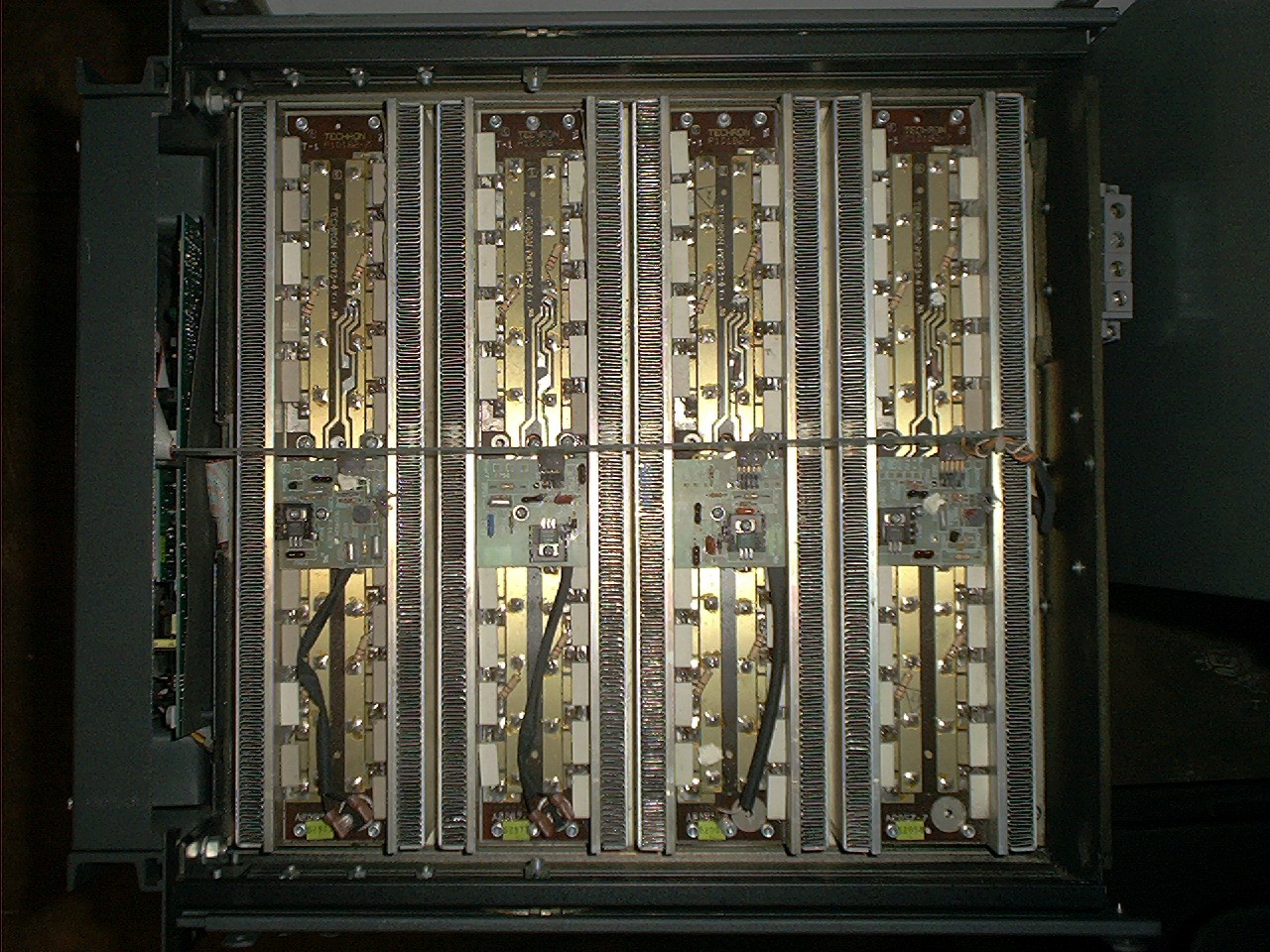
i have an old amplifier using 2N3055
till now, it still working
i give this circuit a job for driving my 6 inch ACR subwoofer 300 watt
also with some modifications
at the power supply i use 3 couples of 4700uF/50v capacitors, 2 couples of 104J capacitors and 1 couple of 47uF/50v capacitor
at the circuit i have been changed 4 capacitors from 3 x 47uF/50v to 22uF/50v and 1 x 47uF/50 to 10uF/50v
Attachments
A couple things I discovered about cascaded (s-Leach) output stages. They must use base stoppers. Many output stages can dispense with them, but this one can't. They are also funny about stray capacitance. If the capacitance between the collector of the lower device and ground is large enough and high-Q the stage will oscillate. More paralleled outputs means more cap. Just the capacitance between the TO-3 cases and heat sink is enough to cause trouble. What got rid of it was to de-Q it by putting a zobel ( .1 uf ceramic disc and a few ohms) from the TO3 case and heat sink. Not on the pcb, not from the terminal on the transistor socket, but directly from the mounting screw to another screw on the heat sink. I could then get away with five pairs and 127 volt rails. Without the zobels (one on each side) it oscillated no matter what else was done.
This is also necessary for class G or H amplifiers, which use some sort of stacked outputs.
This is also necessary for class G or H amplifiers, which use some sort of stacked outputs.
is the heatsink connected to Audio Ground?Just the capacitance between the TO-3 cases and heat sink is enough to cause trouble. What got rid of it was to de-Q it by putting a zobel ( .1 uf ceramic disc and a few ohms) from the TO3 case and heat sink.
The C+R sounds like local supply rail decoupling, but using a very lossy cap.
Did you have to repeat the C+R for every To3 device, uppers and lowers?
i have an old amplifier using 2N3055
till now, it still working
i give this circuit a job for driving my 6 inch ACR subwoofer 300 watt
also with some modifications
at the power supply i use 3 couples of 4700uF/50v capacitors, 2 couples of 104J capacitors and 1 couple of 47uF/50v capacitor
at the circuit i have been changed 4 capacitors from 3 x 47uF/50v to 22uF/50v and 1 x 47uF/50 to 10uF/50v
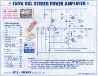
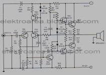
A quick look at that sim and I question a few things.
First that cap shunting the input right there before anything else, with no R to make it a filter. We can't even know what the cutoff frequency is.
Next that C5 blocking cap is only 10n, and with about 33k after it, that cutoff frequency is below 500hz. So I don't even see how full range audio could pass through.
One other thing is the 2N3055 is only TO3 case, while the MJE2955 is only TO220, so that's more than odd, and I don't see this being built for real as is.
No output filter?
No cap on global feedback?
And besides, I found that the diode based current source is among the worst performers...
A couple things I discovered about cascaded (s-Leach) output stages. They must use base stoppers.
We do have base stoppers, and leach made them 10ohms in the most recent super amp.
They are also funny about stray capacitance. If the capacitance between the collector of the lower device and ground is large enough and high-Q the stage will oscillate.
I wonder how those who built it dealt with this.
This mechanical related stuff doesn't show up in sims.
More paralleled outputs means more cap. Just the capacitance between the TO-3 cases and heat sink is enough to cause trouble. What got rid of it was to de-Q it by putting a zobel ( .1 uf ceramic disc and a few ohms) from the TO3 case and heat sink. Not on the pcb, not from the terminal on the transistor socket, but directly from the mounting screw to another screw on the heat sink.
That's interesting. Would you have photos of this to show? How you assembled it would be interesting.
And I second andrew's question: is the sink grounded and to what ground?
Without the zobels (one on each side) it oscillated no matter what else was done.
So every one who built it must've had the same issue.
A quick look at that sim and I question a few things.
First that cap shunting the input right there before anything else, with no R to make it a filter. We can't even know what the cutoff frequency is.
Next that C5 blocking cap is only 10n, and with about 33k after it, that cutoff frequency is below 500hz. So I don't even see how full range audio could pass through.
One other thing is the 2N3055 is only TO3 case, while the MJE2955 is only TO220, so that's more than odd, and I don't see this being built for real as is.
No output filter?
No cap on global feedback?
And besides, I found that the diode based current source is among the worst performers...
first time i read your comment, i think what you have been thinking too before...
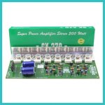
right now and till now this amplifier still working and gives me good sound for driving my 6inch ACR subwoofer 300watt double coils
i am forget, this circuit come to me with stereo module not mono
also, i give you my attachment about the guide from its manufacturer(before my modification) and kit picture itself
Attachments
Last edited:
- Home
- Amplifiers
- Solid State
- Amplifier based on 2N3055