The thing is, the component values are in yellow bg cells and they're values and not formulas, so I can change them, but they're not calculated automatically.
That's correct. This macro creates a VI LOCUS from component values that you enter, unlike MK's analysis, which derives component values from a given locus. Awkward values then ensue, needing series/parallel combinations. I've rearranged MK's analysis to display the locus given standard resistor values. Each component value change modifies that locus to enable it to fit the desired SOA curve on the graph.
I've also devised a macro that calculates component values from the VI locus break points, if you'd prefer that.
MK uses simultaneous equations, but that's not really necessary. Rearrange equations 1 and 3 so that one unknown, say R2, (or equal factor of) is on the LHS of each. Now each RHS is equal. A litttle algebra with the RHS's renders R1 calculable and thus R2. Follow MK's analysis for R4.
We can take this further by pm, if you wish.
Brian.
That's correct. This macro creates a VI LOCUS from component values that you enter, unlike MK's analysis, which derives component values from a given locus.
Then I guess what I'd like to do is the "full circle" thing. We enter the data, such as Vcc, number of pairs, etc... It calculates values, then from those values, we can pick approaching ones that can be obtained standard and then from that the locus can be drawn.
Many diyers out there, even with an excellent paper like Michael's or David's, which describes how to do it, will not be able to do right, at least not with confidence, so that's why having a properly crafted spreadsheet can help. And having such a tool on hand is also nice to avoid having to re-do all the calculations all over again when some small parameter changes.
Awkward values then ensue, needing series/parallel combinations. I've rearranged MK's analysis to display the locus given standard resistor values. Each component value change modifies that locus to enable it to fit the desired SOA curve on the graph.
That's a great tool, but we also need to automate the values calculations, that can serve as a base to pick standard values.
I've also devised a macro that calculates component values from the VI locus break points, if you'd prefer that.
That would be perfect, as that's actually what I'm after. What I had in mind was just that, plus a way to verify and tweak the results afterwards, which is what your sheet does already.
MK uses simultaneous equations, but that's not really necessary. Rearrange equations 1 and 3 so that one unknown, say R2, (or equal factor of) is on the LHS of each. Now each RHS is equal. A litttle algebra with the RHS's renders R1 calculable and thus R2. Follow MK's analysis for R4.
We can take this further by pm, if you wish.
I've been trying to do just that, but as many, I'm not fluent enough with math to do it right, and now with this fig 41 scheme, there is a little more to calculate and I'm to the point where I'm thinking it may require solving 3 equations simultaneously. I've never been good at math, even though I've messed around with some calculus, matrices, kirchhoff, etc.. it didn't stick in my brain and I have to struggle to do anything with that. Actually in this case, I think using kirchhoff's methods would probably be the best way.
I really want to finish that part, so I can move on and finish the pcb layout.
While working on finding a solution to calculate the values in excel, I discovered a tool that should greatly ease and simplify the work. I never even knew that tool existed in excel, so this is entirely new and I need to get my mind wrapped up around that concept as well. That tool is the solver, and I had to enable it because it was never used before.
I wrote down a big bunch of equations in an attempt to solve this, and then tried for a solution with the solver, because I just can't figure out the simultaneous solving. However the results seem odd to me so far, because I get very low values, and although they may be in kohms instead of ohms, I'm not certain what I did was right. It requires verification. I will attempt to do a plot for fig 41 values and we'll see how this works.
I wrote down a big bunch of equations in an attempt to solve this, and then tried for a solution with the solver, because I just can't figure out the simultaneous solving. However the results seem odd to me so far, because I get very low values, and although they may be in kohms instead of ohms, I'm not certain what I did was right. It requires verification. I will attempt to do a plot for fig 41 values and we'll see how this works.
While making calculations and simulations with the protections, I see that in case of a straight short directly on the output, even with protections activating, there is a significant dissipation to deal with in the output transistors' base resistors.
Having retained the 2.2ohms value, and the output's beta droop during the short, those can see some 1.5 to 2amps, which would be quite an overload for any 1/2W or even 1W resistors.
We can't be adding inductance, so using the wire wound types should be avoided there, and they're also big.
There are metal oxyde power resistors that can handle 3-5W, and they too are rather big. I was looking at various options possible on mouser and they have 5W types that are 8mm x 25mm. That can use up some serious pcb real estate in a hurry.
Of course all normal use will not be of any concern, but if we have overloaded parts that can blow during a fault condition, then having protections doesn't really help does it?
Any insight on this topic?
I'm sorry if I am coming back to this again, but I believe the limiter won't be enough on this topology to prevent damage, and this no matter how well we calculate the limiter's values. It's not a matter of where the locus is located, even if we place it very low and it acts far below a normal level of power, I don't think the actual effect from the limiter will be as expected.
I shorted the output with 0.1ohms and took many measurements. The limiter is acting and it seems to work properly, however as I said before, the actual result isn't sufficient to prevent going beyond the soa.
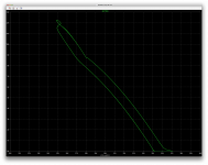
I plotted the soa on one of the transistors (attached) and took a power measurement on it (attached as well), which shows an average power dissipation above 150W and the peaks at more than twice that much.
There is action from the limiter but not enough. I believe this would not protect against a short and many parts would blow.
I measured almost 44A peak in the 50mohms resistor, so we have nearly 2.2V of drop on it, which definitely turns on the protection transistor.
I can see the current in R26 going up to some 30mA, while the protection transistor acts, so T13 is still conducting much more than it should if a limiting action was effective.
I'm thinking that it could be because this quasi topology with the "stacked" emitter resistors presents that drop right below R26, and that this may be why T13 still conducts so much while the protection transistor has tried to short its base. I could be wrong about this, but in any case, whatever locus we calculate for, we're not going to get the exact effect wanted.
I haven't tried that stuff yet on the john ellis bridge, which likely won't react the same because of the complementary topo difference.
It's important obviously that the actual result matches the goal calculated, otherwise it's useless.
Is there something to change to make this behave as expected?
I shorted the output with 0.1ohms and took many measurements. The limiter is acting and it seems to work properly, however as I said before, the actual result isn't sufficient to prevent going beyond the soa.
I plotted the soa on one of the transistors (attached) and took a power measurement on it (attached as well), which shows an average power dissipation above 150W and the peaks at more than twice that much.
There is action from the limiter but not enough. I believe this would not protect against a short and many parts would blow.
I measured almost 44A peak in the 50mohms resistor, so we have nearly 2.2V of drop on it, which definitely turns on the protection transistor.
I can see the current in R26 going up to some 30mA, while the protection transistor acts, so T13 is still conducting much more than it should if a limiting action was effective.
I'm thinking that it could be because this quasi topology with the "stacked" emitter resistors presents that drop right below R26, and that this may be why T13 still conducts so much while the protection transistor has tried to short its base. I could be wrong about this, but in any case, whatever locus we calculate for, we're not going to get the exact effect wanted.
I haven't tried that stuff yet on the john ellis bridge, which likely won't react the same because of the complementary topo difference.
It's important obviously that the actual result matches the goal calculated, otherwise it's useless.
Is there something to change to make this behave as expected?
Attachments
Have you tried Schottky diodes e.g. BAT85 for D5/D6? Or even short them out. This should turn off T13/T14 better under overload conditions.
I thought about testing with germanium diodes, but I haven't found models yet.
I'll look for models of those, and if I can find any, I'll try that. However if works better without diodes but not with the other types, I'm wondering what the solution will be, unless germanium types work any better, as we do need diodes there.
Wouldn't C10 10uF be better across T12 c/e? Not sure why but it doesn't seem right somehow.
That's where I had it before, but then I noticed how the THD was lower on that side, so I left it there. Any specific reason to put it back?
Turns out there was a BAT85 model in cordell's models, so I tried that and it hardly changes anything, there is a noticeable difference, but very tiny and in the end the power dissipated in the same transistor hasn't changed.
Shorting the diodes makes for a higher voltage drop on R26, but hardly changes the output and the dissipation is at least 1W higher in the same output transistor, so that's not going to do it.
I have an idea, that I am about to try now, we'll see how this goes...
Shorting the diodes makes for a higher voltage drop on R26, but hardly changes the output and the dissipation is at least 1W higher in the same output transistor, so that's not going to do it.
I have an idea, that I am about to try now, we'll see how this goes...
I think I would be tempted to put DC into the input at R2 to give a steady few volts DC at the output, add a heavy load that should just go into overload and see what's happening around T32, purely because it's easier to fathom out than with AC. Perhaps temporarily change the 50mohms to 500mohm to keep the current at a safer level.
Ok, my idea didn't work well enough. What I thought was that instead of having the limiter transistors act directly on the pre-driver's bases, it might be more efficient if they acted on the other protection transistors that act on the vas's bases.
This has more of an effect, and there needs to be some additional time constant there to dampen some of the oscillations, however that makes it act somewhat alright within a range of frequencies and not so well at others. The limiter always causes some oscillations due to its normal operation, but those were too much at the higher end of the range. I couldn't make it work properly, so it may not be workable.
One other thing that I tried was to alter the topo to avoid entirely the 50mohms resistors, but then a new set needs to be added on the collectors for the negative side, which adds even more dissymmetry. I thought that there could be a little less of a spread that way for the limiters to "squeeze", but that too wasn't sufficient.
So I'm out of ideas. Removing the diodes causes more trouble and increases dissipation, BAT85 doesn't really change anything. I haven't tried germanium diodes, I'll look for models, just in case.
Basically, I think it won't work because there is only one junction worth of spread to squeeze, and the Vcesat plus the diode must be more than one junction, so the limiter isn't capable of causing enough action to reduce the dissipation. This limiter obviously works better on 2EF or 3EF stages, where there is a much wider spread to squeeze.
Something needs to be done to allow the limiter to act more efficiently on this narrow spread between the bases.
I think I would be tempted to put DC into the input at R2 to give a steady few volts DC at the output, add a heavy load that should just go into overload and see what's happening around T32, purely because it's easier to fathom out than with AC. Perhaps temporarily change the 50mohms to 500mohm to keep the current at a safer level.
As long as C3/C9 are shorted, we should see that dc action. I'll try this now.
I tried a few things with dc applied on the input. I thought using transistors with a lower vcesat would help, so I switched to mpsa06/56, which are supposed to have maximum 0.25V, however they have a lower beta and they don't act hard enough.
So then I switched to bc547c/57c, hoping their higher gain would give them a little more humpf to squeeze those bases, but that's not enough.
I altered the ratio between r62 & r58, so it would act earlier and harder, so I get nearly 700mv of vbe and the limiter transistor sinks 14-15mA, which should cause some limiting action. Still not enough.
I lowered the 10k base resistor to 4k7 so the limiter transistor would saturate harder and this increases its Ic to about 17mA, so it does pull harder, but not really that much so the out still drives quite a current at about 24A (in Re1). This makes (dc) dissipation be about 218W in T21, so this would not limit enough to stay in any soa.
The limiter isn't able to act strongly enough to cause a sufficient limiting.
I couldn't find a germanium diode model with a low forward drop. This might help some, but I doubt it will be enough.
What I did to make it squeeze harder would lower the locus and it would act on legit signals, way before it should act, so this won't work.
This issue probably won't be a concern on the complementary 2EF based version from john ellis. I will try that later, but I'd like to find a workable solution on this elektor based version.
I think we may have to look at other options to protect this amp.
One more thing that I did try, and that kind of works to some limit, is to increase the value of Re1, this gives a little more spread to squeeze for the limiter transistor, and it does have more effect. However it would require a serious increase and this would bring an other quite serious problem, which already exists with a 50mohms value, the heavy dissipation.
In case of a short, assuming the limiter does work as it should and prevent the current from going above the set limit. We have peaks above 30W (20-22W rms) of dissipation in the Re with 50mohms values. The drop is sufficient to activate the limiter and the dissipated power is high, but with TO220 types of power resistors with a heatsink, hopefully not too large for the pcb, it should be manageable. Any increase in Re value will cause far too much dissipation in a fault condition and would require a huge heatsink to prevent damage.
I don't know triacs well enough, but wouldn't those have a low enough saturation drop? Would a triac not latch when acting? can a triac be activated in such a limiter in place of a bjt? just running some ideas.......
What you've done so far ought to work on the face of it, just looking in the T32/T13 general region. However, I think we're forgetting there's huge DC feedback around the whole amp, so anything T32 does will be nulled out to a large extent by T29 trying to pump even more current into T13. Therefore, I think you have to limit the maximum current delivery capability of T29 (and T30 for -ve swings) so that T32 can do its work as intended. i.e. pretend T29 c/e is shorted on a +ve input and follow the current.
What you've done so far ought to work on the face of it,
It really should, but there are "forces" at work that prevent getting the effect expected.
Therefore, I think you have to limit the maximum current delivery capability of T29 (and T30 for -ve swings) so that T32 can do its work as intended. i.e. pretend T29 c/e is shorted on a +ve input and follow the current.
That is what the extra protection transistor T31 on the vas is there for. We don't want it to act on legit signals either, so the way it is set now with 12 ohms to sense on and an idle current close to 12mA in the vas, it has some 150mV of vbe at idle and should act roughly on 4 times the idle current.
I'll try to reduce that high limit, to see how much better limiter action we can get.
Having thought about the triac instead of a bjt for the limiter, which is perhaps not so practical after all, I'm wondering how a mosfet could be used instead of the bjt+diode there. The mosfets have a built-in diode so we don't need to worry about reverse bias, which eliminates the need for the extra diode, and perhaps the turned on drop across the mosfet would be lower than the bjt's vcesat + diode...
I raised R45 from 12ohms to 27, so the vas current now limits lower to about 22mA. I replaced the bc546b by the bc547c for a little higher gain for t31, so it acts a little more strongly to limit current.
There is a little more than 7mA now flowing through r66 and the bulk of it is sunk by t32 as it should.
However this still leaves some 125uA going to t13's base, which is enough to drive t15 and the outputs to overload. So we end up with some 37A through Re1 and the dissipation in the driver and outputs is very high.
This isn't enough for a proper limiting action to stick with the locus intended action.
I shorted the amp's output more strongly with 1mohm and drive the amp with 2V directly on its + input.
With Re1 at 50mohms, we have more than 1.9V drop, which is ample enough to trigger the limiter and we get nearly 750mV vbe on it. I did leave its base resistor at 4k7, correcting the c13 cap to retain the same time constant (it doesn't matter here with dc).
I though about using an even higher gain transistor such as the mpsa18 for the limiter, but then there aren't any complement for that one, so I tried using a 2N5089 instead, and it's not helping.
I thought about using darlingtons, like the mpsa13, but there aren't any complement either, and using a darlington like that would require some 2V to turn it on, and there isn't enough on Re1 at 50mohms for that.
Attachments

The proposed output stage will be fine. This little proof-of-concept 3055 amp had no trouble with a 2 ohm load. Not just a 2 ohm resistor, but a 4 speakers in parallel load. 3 pairs in quasi with a triple. PL400 style, with the upper half an EF3. TIP41 drivers. Front end was simple, just a diff pair and an 8mA VAS, with a current source on each. Probabaly not world-class distortion, but nothing obviously wrong with the sound. At least the proposed improvements are a bunch of cheap small signal devices so the cost to 'improve' it would be a buck or two - but a bit more homework up front to catch 'surprises'.
The trick to getting the grounded bridge to work right is to make sure the front end doesn't depend on a ground reference anyhwere to work right. And that both sides can tolerate sliding rails (very high PSRR and common mode range). It will work like 4 ohms loaded because it's a bridge - but because of the toploogy it is further bridgeable! That means you really want a 2 ohm capable OPS....
I was wondering what you've done with this proto since you tested it. Is it still alive? How long can it run on a 2ohms real world load?
This was that 2 pairs, aiming for 120W on 2ohms right?
I we try to do some basic calculations, we see quickly that a 2ohms load would be too much for 2 pairs, even on resistive load. And this one has no protections.
That proto is still alive - other than bench testing and driving a pair of 2x10's in parallel to see how it sounds and how loud it gets I haven't done much with it. It was 3 pair, not 2. I did end up putting a VI limiter on it - I can dig up the values. It wasn't interfering with normal operation driving four 10's - which is a real world 2 ohm load. It's the type of limiter that needs a ground reference, so it wouldn't necessarily work grounded bridge, but the VI locus would be appropriate to design to. I set it aside for the time being because I'm more interested in getting my little 125-ish-watt one pair class H finished. I had a proto working for that, too.
It was 3 pair, not 2.
For 2ohms load, that's a must.
I did end up putting a VI limiter on it
That's also rather needed, just in case. How was it arranged?
- I can dig up the values. It wasn't interfering with normal operation driving four 10's - which is a real world 2 ohm load.
It would be good info to find out how reactive that is for real. We may be overly pessimistic aiming for 60degrees. However one other thing good to know is how low the impedance drops below nominal.
On the bridge, with 3 pairs, I see we don't have much headroom and setting the locus to hug the soa (DC) doesn't leave much room below for legit signals where the second breakdown is most critical. I've been plotting a 3ohms / 50 degrees load line, which does fit in the soa for 3 pairs and below the locus, but not by much, so if the impendance drops a little below 3ohms and reactance is over 50 degrees, then we have limiter action on legit signal on part of the signal.
125-ish-watt one pair class H finished. I had a proto working for that, too.
Is that one 3055 based? That would also be interesting.
I was even thinking about a leach double barreled with 3055s, how kool would that be?
- Home
- Amplifiers
- Solid State
- Amplifier based on 2N3055