Spookydd, let build something and then measure it.
Don't worry, if you make some mistake.
I hear you.
I have limited tools and means on my end. I have a multimeter and even a scope, but no signal generator and no other measuring instruments, especially no distortion measuring equipment, so doing all those simulations first will improve the end result and reduce the needs for fiddling around with the circuit once built. Also I want to make it as stable as possible virtually, so the chances for oscillations are as low as possible when it's built. I have blown too many expensive transistors in the past, trying to stabilize an oscillating amp (opamp based). I want to make it fun, but not a torture.
Doing simulations doesn't cost anything and that prepares for an easier and better end result.
At my first amp design, I did not using simulator. I forgot put a compensation on VAS. The amp was oscillated. Then I added Miller capacitor, the amp happy and sound nice. But I did not satisfied.
When I using simulator, I spent more time in front of my computer. Do some simulation, and I felt like I built something
When I using simulator, I spent more time in front of my computer. Do some simulation, and I felt like I built something
Hi
I see your challenge is to build a bridge amp. It always struck me that just a simple pair of amps would need a phase inverter to drive them. Why not design a fully differential amp in the first place?
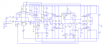
Here's a proposal that is fully DC coupled, has an output servo bias and can deliver 100W into 8 ohms from +/- 35 rails.
To ensure stability it uses input degeneration resistors and inclusive Miller feedback capacitors which gives lower distortion especially around crossover than the standard Miller. This will not have the lowest distortion that might be possible but simulates at 0.014% at 20kHz/100W.
As with all simulations we need to build it and see ...
John
I see your challenge is to build a bridge amp. It always struck me that just a simple pair of amps would need a phase inverter to drive them. Why not design a fully differential amp in the first place?
Here's a proposal that is fully DC coupled, has an output servo bias and can deliver 100W into 8 ohms from +/- 35 rails.
To ensure stability it uses input degeneration resistors and inclusive Miller feedback capacitors which gives lower distortion especially around crossover than the standard Miller. This will not have the lowest distortion that might be possible but simulates at 0.014% at 20kHz/100W.
As with all simulations we need to build it and see ...
John
Attachments
I see your challenge is to build a bridge amp. It always struck me that just a simple pair of amps would need a phase inverter to drive them. Why not design a fully differential amp in the first place?
You've missed part of the discussions earlier in the thread. We're not aiming for an ordinary bridge with 2 identical amps. We're going for a grounded bridge, such as those in most (if not all) of crown's amps. Not quite as simple. There are many very specific considerations.
AND, we're making it all with 3055s.
Here's a proposal that is fully DC coupled, has an output servo bias and can deliver 100W into 8 ohms from +/- 35 rails.
To ensure stability it uses input degeneration resistors and inclusive Miller feedback capacitors which gives lower distortion especially around crossover than the standard Miller. This will not have the lowest distortion that might be possible but simulates at 0.014% at 20kHz/100W.
As with all simulations we need to build it and see ...
This looks interesting, although not the goal that we're aiming for with the grounded bridge.
But I'd like to take a closer look. I can't make out much from the picture posted, the resolution is too low.
Could you post your sim file? (with the models used, to make sure it works the same)
We're on the 3055 thread, so anything based on that is on target.
Actually I've been doing some experiments with various improvements on our chosen topo, and even tried it with a complementary EF3 such as used on the leach amp, to see if I could get something better than our existing quasi, but so far I couldn't match it. This is obviously due to my lack of spice and math skills to get the proper calculations done on compensation and other things like that.
On our quasi topo, with several improvements, mostly from bob cordell's suggestions, I was able to reach a much better thd, in the 0.000xxx, but with the input and output networks disabled, and DC coupled.
We started from an old elektor amp and made small changes here and there to make it work in a grounded bridge topo. This isn't as easy as it seems and both sides of the amp aren't identical.
...and 0.0013% at 1kHz/100W ...
This isn't bad.
I was able to reach this at 4 ohms load at 20khz and 20Vrms output signal level (our full rated goal power). The thing is, I want to make sure all the other aspects of the amp are ok before committing such huge changes. It needs to be double checked for proper roll offs, compensation calculations need to be made to make sure the choices are correct, the stability needs to be checked, square waves tests haven't yet been done, and those could be an issue. The noise is not so much of an issue, as it will be satisfactory as is, especially using the high gain low noise BC550C/60C in the diff amps and keeping the tail currents fairly low.
The behavior on 8ohms load is very nice, but this won't be the way it's used. As a grounded bridge, the amps will always be loaded at 4ohms each (8ohms on the whole bridge). And we're using 3 pairs of 3055s, so it might even be ok on 2ohms load (4 on the whole bridge), but probably with some sag in power level and an increase in thd.
To drive 2 Ohm with 2N3055 with low distortion, I think several alternative for OPS:
1. 2EF, use minimum 4 pair 2N3055 with high hFE driver such as 2SC4793 and 2SA1837
2. 3EF, use minimum 4 pair 2N3055, may be difficult to stabilize them, but take a look 3EF modular design from Ostripper. Currently, I build it but not finish yet.
3. 2EF with CFP or CFP with 2EF, but I don't see such successful solution using CFP with parallel output in these forum.
4. Using error correction, but it seem complex.
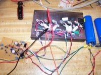
The proposed output stage will be fine. This little proof-of-concept 3055 amp had no trouble with a 2 ohm load. Not just a 2 ohm resistor, but a 4 speakers in parallel load. 3 pairs in quasi with a triple. PL400 style, with the upper half an EF3. TIP41 drivers. Front end was simple, just a diff pair and an 8mA VAS, with a current source on each. Probabaly not world-class distortion, but nothing obviously wrong with the sound. At least the proposed improvements are a bunch of cheap small signal devices so the cost to 'improve' it would be a buck or two - but a bit more homework up front to catch 'surprises'.
The trick to getting the grounded bridge to work right is to make sure the front end doesn't depend on a ground reference anyhwere to work right. And that both sides can tolerate sliding rails (very high PSRR and common mode range). It will work like 4 ohms loaded because it's a bridge - but because of the toploogy it is further bridgeable! That means you really want a 2 ohm capable OPS....
The trick to getting the grounded bridge to work right is to make sure the front end doesn't depend on a ground reference anyhwere to work right. And that both sides can tolerate sliding rails (very high PSRR and common mode range). It will work like 4 ohms loaded because it's a bridge - but because of the toploogy it is further bridgeable! That means you really want a 2 ohm capable OPS....
Attachments
To drive 2 Ohm with 2N3055 with low distortion, I think several alternative for OPS:
Driving 2ohms isn't really the main goal, but while we're at it, with the properly calculated protections, it should do it with the 3 pairs, although with some loss of power and higher thd at high power. My sims showed that it can do it just fine, with losses. The soa being respected, and with a beefy heatsink, this can be done.
A 2ohms load on an amp side would mean a 4ohms load on the bridge, but who has 4 ohms speakers? unless paralleling 2 8ohms speakers, which I wouldn't want to do myself. I'd rather make use of 16ohms speakers...
We're going to aim for a 27amps current limit with the protection circuit, so this will be far enough above needed to drive 4ohms (per amp side) without having the protections starting to act, and if they act on 2ohms at near full power or transients, the thd will go up, but the drive level can be lowered to stay below the distortion increase.
1. 2EF, use minimum 4 pair 2N3055 with high hFE driver such as 2SC4793 and 2SA1837
I'm wary of using exotic parts, such as those often hard to find japanese parts, unless they are also made by western manufacturers and can be easily found.
For now, I'd stick with 3 pairs, but we can look at 4 pairs later for a beefier version for those who really want to drive 2ohms (x2).
Using 2EF with 4 pairs really puts a serious demand on drivers. I haven't seen any that really seem up to the task and those japanese parts may be too hard to find for many.
2. 3EF, use minimum 4 pair 2N3055, may be difficult to stabilize them, but take a look 3EF modular design from Ostripper. Currently, I build it but not finish yet.
We'll look at this option when we get the 3 pairs working. More fun to come later...
I've been simulating with the 3EF such as used in the leach amp, with the complementary 2N/MJ, but not with 4 pairs yet. The changes aren't huge if everything else stays about the same, with only the output stage changing, the design should fairly easily be adapted, so a different version could be made. (later)
3. 2EF with CFP or CFP with 2EF, but I don't see such successful solution using CFP with parallel output in these forum.
Seems a bit complex for diy and hard to get it right.
4. Using error correction, but it seem complex.
Even more complex.
I've been really looking at the nested feedback options, and sometimes it really does bring benefits, but it's complex and since I don't know how to make all the proper calculations, I don't trust tweaked simulations entirely to get this right.
I was able to get thd with 3 zeroes after the . in some configurations, but that was only thd analysis and no other types such as square wave behavior, noise, stability, etc... So it's nice but I don't fully trust my results.
If we can make small improvements on our existing topo and they don't cost much for real benefits, why not make them? let's compare what we can do and get the best we can out of those 3055s, but without going too deep into complexity.
The proposed output stage will be fine.
To stay quasi, I think so.
This little proof-of-concept 3055 amp had no trouble with a 2 ohm load. Not just a 2 ohm resistor, but a 4 speakers in parallel load. 3 pairs in quasi with a triple. PL400 style, with the upper half an EF3. TIP41 drivers. Front end was simple, just a diff pair and an 8mA VAS, with a current source on each. Probabaly not
can you share a schematic? did you simulate it? or just went ahead and built it?
world-class distortion, but nothing obviously wrong with the sound. At least the proposed improvements are a bunch of cheap small signal devices so the cost to 'improve' it would be a buck or two - but a bit more homework up front to catch 'surprises'.
That's what I think. If we can make serious improvements with a few extra cheap parts, then we should do it. That's why I was trying to add current mirrors on our work in progress, and then 2 transistor vas and then added cascode on the vas. All that does bring in some benefits, but the compensations also need to be done right and that may bring even more benefits once properly nailed down.
The trick to getting the grounded bridge to work right is to make sure the front end doesn't depend on a ground reference anyhwere to work right.
That's what we've been doing, and I don't think we can do away with the global feedback referencing to ground, that can't be done any other way.
Getting a grounded bridge working is a nice exercise and out of the ordinary. I can't wait to have that built.
And that both sides can tolerate sliding rails (very high PSRR and common mode range). It will work like 4 ohms loaded because it's a bridge - but because of the toploogy it is further bridgeable! That means you really want a 2 ohm capable OPS....
YES, that's the very cool thing about grounded bridges, although a tricky thing to do, with the proper isolation of the grounds between the bridges.
Each amp side driving a 4 ohms load, we're driving an 8ohms load on the bridge at 200Wrms nominal, with quite decent thd at that power level. If we bridged again 2 grounded bridges, assuming no sagging on power when the 2ohms load is imposed on each grounded bridge side, then we're at 800W isn't it? (on 8ohms) All that on rails of only 35V!!! and with 3055s, very cool!
Spookydd
The beauty of the differential design is that if you want one side of the bridge grounded (say the negative output) then ground it but disconnect the ground on the power supply so it can float.
You then have your grounded bridge amp. Distortion might be lower with differential input signals but you can still drive it from one side with 2x voltage.
John
...and the inclusive Miller won't mind if you use quasi (all 3055) output. I'd recommend at least 3 pairs of 3055's per output side and a triple Darlington for driving e.g. BD139-MJE15032-2N3055x3 but I haven't explored the optimum arrangement for the "PNP" output configuration. My guess is that it would be e.g. BD140-MJE15032-2N3055x3.
John
John
The beauty of the differential design is that if you want one side of the bridge grounded (say the negative output) then ground it but disconnect the ground on the power supply so it can float.
Normally with a grounded bridge, there is no ground at the psu, as it's made simpler (one of the "features" of the grounded bridge) without a center tap on transformers and the rails are not hinging around a ground that the psu makes, but rather the amp is "attached" to and forces the rails to swing around that.
The transformer only needs a single winding, the psu only needs a single rectifier bridge and a single bank of filter caps.
One thing that can be done with such an arrangement, with the grounds properly managed, is that 2 grounded bridges can again be bridged. But that requires some serious care with the wiring and not mixing up each bridge's grounds.
...and the inclusive Miller won't mind if you use quasi (all 3055) output. I'd recommend at least 3 pairs of 3055's per output side and a triple Darlington for driving e.g. BD139-MJE15032-2N3055x3 but I haven't explored the optimum arrangement for the "PNP" output configuration. My guess is that it would be e.g. BD140-MJE15032-2N3055x3.
It'll be interesting to experiment with this.
Aren't the bd139/40 a little too slow though? and rather low gain too.
I've been testing various types for the pre-drivers and vas, but the faster ones also are causing oscillation issues.
sorry I forgot ... the grounded reference input resistor to the bias servo has also to be disconnected from ground and wired to the centre tap of the power supply voltage....
That would be difficult if we have a psu made as it should for a grounded bridge, without the center tap/ground.
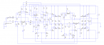
It now looks like this ...
This is a spice sim. Is it made with ltspice? can you share it?
I'd like to play around with this.
- Home
- Amplifiers
- Solid State
- Amplifier based on 2N3055