I wonder how those who built it dealt with this.
This mechanical related stuff doesn't show up in sims.
There was probably a lot of head scratching. Depending on how much parasitic a given layout had you would have varying degrees of success. Of course the simulator shows nothing. Some would get lucky, others would not.
And I second andrew's question: is the sink grounded and to what ground?
So every one who built it must've had the same issue.
The heat sinks were foot-long extrusions bolted in a clam shell and to the chassis. They pretty much had to be grounded. I played around with a high power class H where I let the heat sink float up to the (moving) rail voltage. More trouble than it was worth so I bit the bullet and ordered sil-pads and added the darn RCs. No issues with grounding the heat sink if the mid rail had a snubber across the commutating diode and the zobel to ground on the collectors.
Spooky's other favorite circuit (the grounded collector BJT transnova circuit) can dispense with this problem because the rail connects to the emitters. QSC's classic version rarely gives any trouble and can run class H without any special treatment. I'm confident it could be easily cascoded as well.
A quick look at that sim and I question a few things.
First that cap shunting the input right there before anything else, with no R to make it a filter. We can't even know what the cutoff frequency is.
Next that C5 blocking cap is only 10n, and with about 33k after it, that cutoff frequency is below 500hz. So I don't even see how full range audio could pass through.
One other thing is the 2N3055 is only TO3 case, while the MJE2955 is only TO220, so that's more than odd, and I don't see this being built for real as is.
No output filter?
No cap on global feedback?
And besides, I found that the diode based current source is among the worst performers...
Once again...
I live in Indonesia and many people using this type of amplifier using 2N3055 and MJE2955
Not only for home amplifier, many car amplifier using this too
Not only them, some Sound System for ceremony, wedding etc using it too for driving their medium and twitter speakers(active crossover system only)...
So, don't judge this circuit is impossible for real...
Many factor as reason, but there are 3 reasons as general factor
First we need powerful amplifier but cheap also easy for looking sparepart and repairing
Second, we need amplifier that so easy for build
Third, different country different style different technology ability
If you lived in USA and can easily building class D, G, H amplifier etc but not like us who are living in INDONESIA
Once again...
I live in Indonesia and many people using this type of amplifier using 2N3055 and MJE2955
Not only for home amplifier, many car amplifier using this too
Not only them, some Sound System for ceremony, wedding etc using it too for driving their medium and twitter speakers(active crossover system only)...
Nothing wrong with that. And proves a point I made earlier that there is even today still lots of people on this planet who do want to build such amps and using those old but trusty 3055s. I also myself want to play with them and build some amps, using interesting topologies like grounded bridge, grounded collector and so on.
So, don't judge this circuit is impossible for real...
I'm not, but some data posted just can't be as they are stated that's all. For one thing, we see a 300W power stated on that kit. I don't know what that sx270 actually is, but that surely can't be that 3055 amp with rails at 30-42V.
And that schematic with 150W OCL (what does OCL mean anyway?), with 3055s and rails at 24V, surely can't put out 150W for real, at least certainly not on 8ohms, and if dropping the load impedance to reach that power level, then it would surely blow up the outputs before reaching that power level, with only a single pair of them.
Many factor as reason, but there are 3 reasons as general factor
First we need powerful amplifier but cheap also easy for looking sparepart and repairing
Second, we need amplifier that so easy for build
Third, different country different style different technology ability
That's cool, and ,more reasons why we're working on designs on this thread that are filling this "need", while exploring interesting topologies that haven't been tried long ago when those old 3055s were so popular.
Now we can get much more power from those 3055s than ever before.
I'd love to see our grounded bridge working and especially would really like to see how it performs once it's made into a bridged bridge (4 amps).
If you lived in USA and can easily building class D, G, H amplifier etc but not like us who are living in INDONESIA
I hear you!
")
And that was my point in a response to Bob Cordell earlier. There ARE people who DO want to build those amps, with the 3055s, and it's interesting, and useful.
I've been thinking about our ongoing current design right now for a grounded collector design. What if we adapted one to make use of the 3055/2955 trannies? Wouldn't that be nice as well?
With the grounded collector topo, all TO3 cases would just mount as is on heatsinks, with just good thermal paste, which allows getting more out of those 3055s. Of course this can't be done with a quasi, but a good complementary topo with 3055/2955 is feasible.
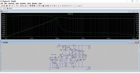
The bootstrapping on fandi's amp gives it an odd LF response.
There you go
It doesn't take much to realize some details are wrong and values need adjustments.
It must sound "weird" as is. At least the bass level must be way off, and even sound weak.
That cap at the input can't be right.
I understand using different models in sims if you don't have the right ones on hand, but a real build obviously couldn't be done that way (mixing TO3s with TO220s for example).
I wonder what a tian probe would reveal, with no output coil/zobel, and no global feedback?
The cap at the input does look a bit on the low side, however it appears that the input resistor R18 is in fact bootstrapped using the 680R negative feedback resistor R17 (referring to Mooley's "draft 2" schematic above).... This makes the input impedance considerably higher that it seems at first glance. So that value probably quite in order!
Last edited:
The bootstrapping on fandi's amp gives it an odd LF response.
Hi...
We meet again...
At my last thread, your solution is working and great
On this amplifier about this.bootstarapping is odd?
Not only you, me too...
Tull now, i am still confused
At simulation we get bad result bad in real life, reality so different...
Nothing wrong with that. And proves a point I made earlier that there is even today still lots of people on this planet who do want to build such amps and using those old but trusty 3055s. I also myself want to play with them and build some amps, using interesting topologies like grounded bridge, grounded collector and so on.
I'm not, but some data posted just can't be as they are stated that's all. For one thing, we see a 300W power stated on that kit. I don't know what that sx270 actually is, but that surely can't be that 3055 amp with rails at 30-42V.
And that schematic with 150W OCL (what does OCL mean anyway?), with 3055s and rails at 24V, surely can't put out 150W for real, at least certainly not on 8ohms, and if dropping the load impedance to reach that power level, then it would surely blow up the outputs before reaching that power level, with only a single pair of them.
That's cool, and ,more reasons why we're working on designs on this thread that are filling this "need", while exploring interesting topologies that haven't been tried long ago when those old 3055s were so popular.
Now we can get much more power from those 3055s than ever before.
I'd love to see our grounded bridge working and especially would really like to see how it performs once it's made into a bridged bridge (4 amps).
I hear you!
And that was my point in a response to Bob Cordell earlier. There ARE people who DO want to build those amps, with the 3055s, and it's interesting, and useful.
I've been thinking about our ongoing current design right now for a grounded collector design. What if we adapted one to make use of the 3055/2955 trannies? Wouldn't that be nice as well?
With the grounded collector topo, all TO3 cases would just mount as is on heatsinks, with just good thermal paste, which allows getting more out of those 3055s. Of course this can't be done with a quasi, but a good complementary topo with 3055/2955 is feasible.
I have no much words but i realize the reality...
About 24vCT - 35vDC we can reach 300 stereo or mono 150 watt using 10Amps CT trafo
But that's what i know...
About the picture with one rail?
That's just guide, on the board PCB circuit come with 2x2N3055 and 2xMJ2955 per channel...
Look at 3 pictures i have been attached before
At third picture, you can see real product then look at heatsink, there are 8 big transistors
It means 2x2N3055 and 2xMJ2955 per channel
The full descriptions the box case
Sorry if i don't put it here
About final transistors mounted of heatsink, i don't know why
That's have been being style in my country
Many circuits, even TIP31 they put mounted of heatsink
That's all i can said, nothing else
The other, i am agree with you...
what is your dual rail voltage? what is your speaker impedance?..................
About 24vCT - 35vDC we can reach 300 stereo or mono 150 watt using 10Amps CT trafo.....................
Hi...
We meet again...
At my last thread, your solution is working and great.
It seems that way
Pleased to hear your other amp is OK.
Your simulation file uses a 10nf for the input cap. The diagrams in post #620 show a 100nf which would be like this:
Attachments
what is your dual rail voltage? what is your speaker impedance?
My dual rail voltage AC 24-CT-24
After bridge caps reach DC 35-0-35
10 amps
My speake impedance 4 ohm
It seems that way
Pleased to hear your other amp is OK.
Your simulation file uses a 10nf for the input cap. The diagrams in post #620 show a 100nf which would be like this:
Thank you man..
I will.check it out again
If that's wrong, i will fixing it again
About 24vCT - 35vDC we can reach 300 stereo or mono 150 watt using 10Amps CT trafo
But that's what i know...
With 24V before rectifying, with the little excess voltage from no load, you might get something like 35V, maybe, maybe not quite, if you count the little overhead from the rectifiers, and then under load, there is no way even with a beefy transformer that it would keep 35V on the rails. It would certainly sag.
Then the amp has its own little "overhead", with the Vcesat and drops in the resistors, even if you managed to keep the rails near 35V under full load, which is unlikely with no regulation and only 24V at the transformer, you may get a peak output voltage on the load at some 30V or so, which is just a little more than 21V rms (sine).
On 8ohms, some 21V rms is only about 56W rms. Nowhere near 150W, and certainly not 300W.
Now if you're talking about bridging, that's an other story, but not on a single 3055 amp with 35V rails at most.
Your watts are vaporware.
That's just guide, on the board PCB circuit come with 2x2N3055 and 2xMJ2955 per channel...
2 pairs are better than one, and it can handle more load, but still won't increase the available voltage swing. With 2 pairs, maybe the 4ohms load might not kill it too fast, but then the rails will sag more, with less voltage swing, you will not even double the 8ohms power, so you're still at some ~100W(ish...), not 150 and not 300.
Look at 3 pictures i have been attached before
At third picture, you can see real product then look at heatsink, there are 8 big transistors
Yes, that looks different from what the schematic says.
It means 2x2N3055 and 2xMJ2955 per channel
The full descriptions the box case
Sorry if i don't put it here
So that's 2 power amps per pcb then, with 2 pairs of 3055s per amp.
Perhaps they get bridged into a single amp, but you wouldn't want to load that bridge with any less than 8ohms. And then you might get some 200W, maybe, assuming the rails don't sag too much.
If bridged, then the 150W are possible, but not 300W unless you drop the load on the bridge to 4ohms, which would certainly kill the amps with only a couple of pairs of output.
We don't need to make any calculations and check SOA for that. 2 pairs of 3055s just don't have enough SOA to handle 2ohms load.
Your simulation file uses a 10nf for the input cap. The diagrams in post #620 show a 100nf which would be like this:
Better that way, but still not so hifi with the low end of the bandwidth being a little high.
My dual rail voltage AC 24-CT-24
After bridge caps reach DC 35-0-35
With no load!
10 amps
Maybe available from the transformer, but I suspect not the load at which you have those 35V.
My speake impedance 4 ohm
On one amp? Or on a bridge?
If on the bridge, you're really pushing those 3055s hard, and in any case, not getting 300W for sure.
Rails will sag. And if pushed a little hard, the amps could blow.
Better use heavy duty heatsinks to limit the chances for a blow up.
With 24V before rectifying, with the little excess voltage from no load, you might get something like 35V, maybe, maybe not quite, if you count the little overhead from the rectifiers, and then under load, there is no way even with a beefy transformer that it would keep 35V on the rails. It would certainly sag.
Then the amp has its own little "overhead", with the Vcesat and drops in the resistors, even if you managed to keep the rails near 35V under full load, which is unlikely with no regulation and only 24V at the transformer, you may get a peak output voltage on the load at some 30V or so, which is just a little more than 21V rms (sine).
On 8ohms, some 21V rms is only about 56W rms. Nowhere near 150W, and certainly not 300W.
Now if you're talking about bridging, that's an other story, but not on a single 3055 amp with 35V rails at most.
Your watts are vaporware.
2 pairs are better than one, and it can handle more load, but still won't increase the available voltage swing. With 2 pairs, maybe the 4ohms load might not kill it too fast, but then the rails will sag more, with less voltage swing, you will not even double the 8ohms power, so you're still at some ~100W(ish...), not 150 and not 300.
Yes, that looks different from what the schematic says.
So that's 2 power amps per pcb then, with 2 pairs of 3055s per amp.
Perhaps they get bridged into a single amp, but you wouldn't want to load that bridge with any less than 8ohms. And then you might get some 200W, maybe, assuming the rails don't sag too much.
If bridged, then the 150W are possible, but not 300W unless you drop the load on the bridge to 4ohms, which would certainly kill the amps with only a couple of pairs of output.
We don't need to make any calculations and check SOA for that. 2 pairs of 3055s just don't have enough SOA to handle 2ohms load.
I don't talking about bridge...
This circuit come with stereo channel...
I mean 300 watt is stereo not mono
If this vaporware, this circuit will die 5 years ago...
But, reality tells other
Till now, this still working
I know about my Speaker load, i have been tested using my friend amplifier
But his.amplifier.game over and producing white smoke
My speaker load 1 subwoofer 8ohm 300watt double coils and 2woofer 8ohm 300watt
It seems that way
Pleased to hear your other amp is OK.
Your simulation file uses a 10nf for the input cap. The diagrams in post #620 show a 100nf which would be like this:
Oohhh...
This is from the manufacturer...
After turning on for some days, i don't get good sound
So i call my friend(using same amplifier but with some modification) then testing it
After some time, we make some decisions
But i.have another idea based on my experience
Not changing too many components, but just little that can give better.result
That's the story why my LTSpice is so different from mufacturer
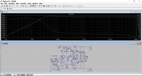
Better that way, but still not so hifi with the low end of the bandwidth being a little high.
Yes, it could be improved quite a lot. Removing the bootstrap would see a normal roll of in LF response beginning from around 200Hz.
Oohhh...
This is from the manufacturer...
After turning on for some days, i don't get good sound
So i call my friend(using same amplifier but with some modification) then testing it
After some time, we make some decisions
But i.have another idea based on my experience
Not changing too many components, but just little that can give better.result
That's the story why my LTSpice is so different from mufacturer
LTspice will be different on things like bias current and DC offset, because those things depend so much on the actual transistors used.
The overall frequency response should be pretty accurate in simulation though, no matter what devices you use.
My dual rail voltage AC 24-CT-24
After bridge caps reach DC 35-0-35
10 amps
My speake impedance 4 ohm
I don't talking about bridge...
....................
I mean 300 watt is stereo not mono
..................
Lies and damned lies from your retailer/manufacturer..................
Your watts are vaporware...................
150W into 4r0 requires an output of 34.64Vpk
you can't get that from ±35Vdc supply rails.
You should know that BEFORE you bought it, 5years ago.
And certainly have learned about power ratings in the intervening period.
- Home
- Amplifiers
- Solid State
- Amplifier based on 2N3055