Workhorse said:Your Vgs is quite low, then its difficult to opt my circuit for your laterals...
Though you might try this as well....
Thanks, it now looks even closer to my circuit...except for your CB...
so how to minimize cross-conduction at HF?
fab said:
Thanks, it now looks even closer to my circuit...except for your CB...
so how to minimize cross-conduction at HF?
Use Baker Clamp....
Workhorse said:Why dont you use Vertical mosfets, as they are easily available....
Because I already have expensive mathed to-3 laterals that I want to use in an already adapted chassis (Hafler DH-200). Also, they are better regarded for audio than verticals...
fab said:
Also, they are better regarded for audio than verticals...
I donot agree.....that lateral are better than verticals.....in audio
Actually my circuit was for vertical mosfets not for lateral types, but you can also use laterals but withsome aforementioned modifications.....
you can use baker clamp to reduce the Cross-conduction when clipping in HF occurs.. on the collectors of CB stage transistors using fast recovery diodes....
Re: Kanwar Circuit
Hi FAB,
The CB stage doesnot invert the phase, the phase inversion takes place at the output stage with mosfets in common source configuration...
Yes, the CB stage is of much significance in my circuit...
1. It helps in providing the level shifting of signal..
2. It provides voltage gain
3. It is fast because of absence of miller effect, thus giving high slewrate
4. It doesnot stick the waveform to its rail in the case of Clipping, so there is no need of extra anti-saturation diodes ...
5. It act as a summing junction for local feedback loop, which again linearizes the output signal...
hope that helps...
K a n w a r
fab said:In your circuit, I have just noticed the special "inverting" op-amp configuration that is required because the CB stage inverts the signal...
Is the CB stage an important key of the performance of your circuit?
Hi FAB,
The CB stage doesnot invert the phase, the phase inversion takes place at the output stage with mosfets in common source configuration...
Yes, the CB stage is of much significance in my circuit...
1. It helps in providing the level shifting of signal..
2. It provides voltage gain
3. It is fast because of absence of miller effect, thus giving high slewrate
4. It doesnot stick the waveform to its rail in the case of Clipping, so there is no need of extra anti-saturation diodes ...
5. It act as a summing junction for local feedback loop, which again linearizes the output signal...
hope that helps...
K a n w a r
Re: Re: Kanwar Circuit
Hi Kanwar,
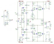
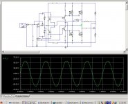
I have simulated your circuit (http://www.diyaudio.com/forums/showthread.php?postid=1105696#post1105696 ) w/o the op-amp input to show you what I mean. First the circuit...
Workhorse said:
Hi FAB,
The CB stage doesnot invert the phase, the phase inversion takes place at the output stage with mosfets in common source configuration...
Hi Kanwar,
I have simulated your circuit (http://www.diyaudio.com/forums/showthread.php?postid=1105696#post1105696 ) w/o the op-amp input to show you what I mean. First the circuit...
Attachments
Workhorse said:Could you tell me which opamp , BJT models did you use in your simulation.....
I use the models that I have (opamp LF351, bjt 2n2222a, 2n2907, generic mosfet with custom adjusted VGSoff to 0.5v) and usually it does the job...
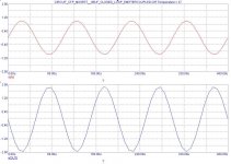
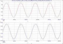
Workhorse said:I have got rail to rail swing with +-60 rails easily
In http://www.diyaudio.com/forums/showthread.php?postid=1106511#post1106511 ,
I think R110 was much too low...I changed it to 47k and now it works!
In fact I am not sure what should be the "best" value for R110 and R114. In this configuration what is really the CFP gain ?
Attachments
fab said:
I use the models that I have (opamp LF351, bjt 2n2222a, 2n2907, generic mosfet with custom adjusted VGSoff to 0.5v) and usually it does the job...
you should try to add some more JFET op-amps and other op-amps to your models
LF351 - Wide Bandwidth JFET Input Operational Amplifier [Discontinued]
- The LF351 is a low cost high speed JFET input operational amplifier
it is so old, that with wide Bandwidth they mean the following:
• Wide gain bandwidth: 4 MHz
• High slew rate: 13 V/µs
• Low supply current: 1.8 mA
• Low input noise voltage: 25 nV
Even if the old LF351 is not a bad op-amp,
neither 4 MHz or 25 nV noise are very impressive values.
Not even for audio applications = low frequency.
Regards
lineup
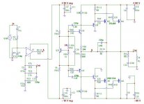
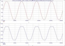
Workhorse said:In my simulation I used 3.3k and 47k respectively to achieve rail to rail output...my simulation shows the gain is around 47K/3.3K=14 typically...only a near assumption though
Is there a practical way to hve this configuration to work with a lower CFP "local" feedback gain for the goal of having the output section more invariant to load impedance (that is the goal of my initial circuit with low LOCAL feedback gain)? I guess that would mean to increase substancially the output section open loop gain... With high gm mosfet transistors (vertical) that is less of a problem then with low gm ones (lateral)....
lineup said:
you should try to add some more JFET op-amps and other op-amps to your models
it is so old, that with wide Bandwidth they mean the following:
• Wide gain bandwidth: 4 MHz
• High slew rate: 13 V/µs
• Low supply current: 1.8 mA
• Low input noise voltage: 25 nV
Even if the old LF351 is not a bad op-amp,
neither 4 MHz or 25 nV noise are very impressive values.
Not even for audio applications = low frequency.
Regards
lineup
Hi lineup,
thanks to remind me to pay more attention to the model I use...it is just that I could not find additional models for my old Microcap 6 version...Also, I am not that familiar to add new models in this software...(except adding all parameters manually which is a pain since the terminology used in the software is confusing with the one I learned or found in the datasheets...
fab said:
Is there a practical way to hve this configuration to work with a lower CFP "local" feedback gain for the goal of having the output section more invariant to load impedance (that is the goal of my initial circuit with low LOCAL feedback gain)? I guess that would mean to increase substancially the output section open loop gain... With high gm mosfet transistors (vertical) that is less of a problem then with low gm ones (lateral)....
Exactly! Yeah that circuit was actually devised for Verticals only....
- Status
- This old topic is closed. If you want to reopen this topic, contact a moderator using the "Report Post" button.
- Home
- Amplifiers
- Solid State
- AMP with inverting output stage mosfet