Re: Updated output
fab.
Okay, use the resistor values that will work.
You are the one that would know best.
And you can run the Simulations, too see the results.
My suggestion was Without Buffer transistors: Q36 Q37.
These buffers will allow higher value resistors, this is only a good thing.
I think your latest schematic looks good.
I downloaded and saved it in my /diyaudio-persons/fab folder")
Where I have ALL the versions you have posted of this amplifier.
Regards
lineup
fab said:Hi lineup and ilimzn
This is what I came up based on your comments. I kept the drain resistors for now...
I can not have only 47 + 39 ohms in the dividers b/c of the high power of the amp....
fab.
Okay, use the resistor values that will work.
You are the one that would know best.
And you can run the Simulations, too see the results.
My suggestion was Without Buffer transistors: Q36 Q37.
These buffers will allow higher value resistors, this is only a good thing.
I think your latest schematic looks good.
I downloaded and saved it in my /diyaudio-persons/fab folder
Where I have ALL the versions you have posted of this amplifier.
Regards
lineup
Re: version w/o extra buffer
I think you should keep Q36 Q37 buffers for Gates.
It is not good to let Output Stage do high % of the amp total voltage gain.
Because this gain has got not same QUALITY,
as for example INPUT Stage.
The trick is to make the INPUT stage do as much of the gain
as possible,
But not that much of it that input stage start making a BAD JOB.
Because input stage transistors, are The Faster ones ( fT 300MHz ).
They are often also working in a more linear region
of amplification. At those currents they operates.
lineup
fab said:This one with a single feedback resistor
does not require the extra buffer but more gain...to get same output...
I think you should keep Q36 Q37 buffers for Gates.
It is not good to let Output Stage do high % of the amp total voltage gain.
Because this gain has got not same QUALITY,
as for example INPUT Stage.
The trick is to make the INPUT stage do as much of the gain
as possible,
But not that much of it that input stage start making a BAD JOB.
Because input stage transistors, are The Faster ones ( fT 300MHz ).
They are often also working in a more linear region
of amplification. At those currents they operates.
lineup
Re: Updated output
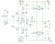
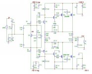
Sorry I had a divider (input filter) in the input section too high for the impedance of the this CFP stage. I knew that the simulation was wrong the the theory of the gain was right:
CFP gain = 1 + R110 / R80 ( approximation since the open loop gain is not that high...)
So I get back to my divider with a gain of about 2 since I do not need 60V output and I want to limit the risk of oscillation as much as possible...Anyway, the power supply will drop problably at about 56v with both channel driven and if we add the Vds drop with a high RDSon (lateral mosfet) at high output current then 50Vac or so signal amplitude is quite OK.
fab said:This is what I came up based on your comments. ....
Sorry I had a divider (input filter) in the input section too high for the impedance of the this CFP stage. I knew that the simulation was wrong the the theory of the gain was right:
CFP gain = 1 + R110 / R80 ( approximation since the open loop gain is not that high...)
So I get back to my divider with a gain of about 2 since I do not need 60V output and I want to limit the risk of oscillation as much as possible...Anyway, the power supply will drop problably at about 56v with both channel driven and if we add the Vds drop with a high RDSon (lateral mosfet) at high output current then 50Vac or so signal amplitude is quite OK.
Attachments
lineup said:How much will you bias MOSFET 2SK134 / 2SK49 ?
Because I suppose you will be running in Class AB.
From what I have read in several different articles,
something like 90-100 mA per device
is what good designers use.
Hi lineup
Of course class AB (DH-220 chassis with +/-60 Vdc !!!).
I use about 120ma per device (after the change of slope of temperature coefficent...)
I already have a "big" AMP having class A (15Wrms) + AB (70Wrms) / 8 ohms (see my picture web page...) with 5 x 2SK1058/2SJ162
Hi Fab & Lineup,
Have a look at this circuit...
It features opamp frontend and CB stage coupled with inverse driver to drive the Comp.MOSfets in Common Source configuration...A local and a Global feedback loop for linearization....All BJTs are small signal 2N5551/5401 types or similar....output devices are vertical mosfets IRF640/9640 ones
I have used this in my low power amps upto 500W with no cross-conduction at 50KHZ at all, also its slew rate is 75V/uS with +-65V rails....
K a n w a r
Attachments
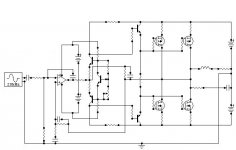
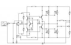
Workhorse said:Hi Fab & Lineup,
It features opamp frontend and CB stage coupled with inverted driver
to drive the Compl. MOSFETs in Common Source configuration...
A local and a Global feedback loop for linearization....
All BJTs are small signal 2N5551/5401 types or similar....
output devices are vertical mosfets IRF640/9640 ones
I have used this in my low power amps upto 500W with no cross-conduction at 50KHZ at all, also its slew rate is 75V/uS with +-65V rails....
K a n w a r
Thanks Kanwar!
Sure is on topic. Using MOSFETs with Output taken from Drains.
About IRF640 / IRF9640, TO-220 HEXFETS:
They are probably the best TO220 IRF devices we can find.
I am surprised they are not more often used ......
I saved your simplified circuit, in my folder
/My documents/diypersons/Workhorse/
Questions:
1. Is there any special op-amp you have used and
can recommend for this application?
2. How much current do you use for driving the MOSFET Gates?
Regards
lineup
 will never in his life have the money to visit India
............................................................................................
India one of the oldest cultures of mankind
India have so many people, human resources, they can outperform any western country
India together with China will be major regions for future world economy!
Workhorse said:Hi Fab & Lineup,
Have a look at this circuit...
It features opamp frontend and CB stage coupled with inverse driver to drive the Comp.MOSfets in Common Source configuration...A local and a Global feedback loop for linearization....All BJTs are small signal 2N5551/5401 types or similar....output devices are vertical mosfets IRF640/9640 ones
I have used this in my low power amps upto 500W with no cross-conduction at 50KHZ at all, also its slew rate is 75V/uS with +-65V rails....
K a n w a r
Hi kanwar
The CFP parts is quite interesting...is similar to mine but different since VGSoff of the IRF are higher and transconductance higher too.. this reminds a bit of SKA amp output (buffer + mosfet)...
Can you comment my circuit
lineup said:
Thanks Kanwar!
Sure is on topic. Using MOSFETs with Output taken from Drains.
About IRF640 / IRF9640, TO-220 HEXFETS:
They are probably the best TO220 IRF devices we can find.
I am surprised they are not more often used ......
I saved your simplified circuit, in my folder
/My documents/diypersons/Workhorse/
Questions:
1. Is there any special op-amp you have used and
can recommend for this application?
2. How much current do you use for driving the MOSFET Gates?
Regards
lineup
Thanks Lineup,
This circuit works best with OPA2134, NE5532, LM837, MC33079...works worst with TL074....
The Class-A buffer EF stage idle current is 25mA, since the drivers are in inverse follower modes they dissipate very little 35mW max...All the dissipation is served by the resistor itself...
For much lower power versions IRF540/9540 could also be used...
regards,
K a n w a r
fab said:
Hi kanwar
The CFP parts is quite interesting...is similar to mine but different since VGSoff of the IRF are higher and transconductance higher too.. this reminds a bit of SKA amp output (buffer + mosfet)...
Can you comment my circuit
The driver stage in your amp is CE which is prone to oscillations with HF , also Cross-Conduction is likely to happen above 25khz and large clip sticking during saturation because of charge storage effects....
If you look in my circuit it uses CB which is much faster because of absence of Miller effect and there is no cross-conduction at HF...
regards,
K a n w a r
Also, The Turn-off of mosfets in your circuit is passive and Turn-ON is active, which again contributes to cross-conduction at HF, while you can eventually see in my circuit turn-off is faster and active while turn-on is slower and passive with simple resistor...
Also it improves the capacitive load handling
Also it improves the capacitive load handling
Re: Kanwar comments
Yes, it could be very well adapted for the Lateral Mosfets...but given the threshold gate voltage for mosfet should be atleast 1.5 volts minimum or you have to change the EF driver to a regular one...
fab said:Thanks Kanwar
Can your design be adapted to lateral mosfets?
Yes, it could be very well adapted for the Lateral Mosfets...but given the threshold gate voltage for mosfet should be atleast 1.5 volts minimum or you have to change the EF driver to a regular one...
Re: Re: Kanwar comments
You mean removing the EF driver? if so I am getting back to square one where a 50 ohms mosfet drive resistor and the CFP divider power dissipation...
Workhorse said:
Yes, it could be very well adapted for the Lateral Mosfets...but given the threshold gate voltage for mosfet should be atleast 1.5 volts minimum or you have to change the EF driver to a regular one...
You mean removing the EF driver? if so I am getting back to square one where a 50 ohms mosfet drive resistor and the CFP divider power dissipation...
Workhorse said:Not removing EF stage , could you tell me what is the V gate threshold for your laterals....
2SK134 = 2SK1058
To bias it at about 110ma I need about 0.7Vdc
- Status
- This old topic is closed. If you want to reopen this topic, contact a moderator using the "Report Post" button.
- Home
- Amplifiers
- Solid State
- AMP with inverting output stage mosfet