fab said:
Hi lineup,
thanks to remind me to pay more attention to the model I use...
it is just that I could not find additional models for my old Microcap 6 version...
Also, I am not that familiar to add new models in this software...
Yeah, I know. I have a bit same problem with my Sim.
Because I downloaded a 'cracked' free version, this had very few models in library.
And not too many good for Audio.
Now, my simulator has got a TOOL: New Part Wizard.
So if I have found some spice model file at web search I can create a new part with this model.
I just 'paste' the model data into this Wizard
and add the new part to my library.
Advice:
You should read the HELP guide in your MicroCap.
About how to add new components/models.
If we are too lazy to read HELP, we will not learn to use software fully
")
I am afraid this is a fact!
lineup
-----------------------------------------------------------
Try to find 'spice model' for TL071.
This JFET would be easy to find model for and I think is a 'step up' compared to old LF351.
fab said:
Is there a practical way to hve this configuration to work with a lower CFP "local" feedback gain for the goal of having the output section more invariant to load impedance (that is the goal of my initial circuit with low LOCAL feedback gain)? I guess that would mean to increase substancially the output section open loop gain... With high gm mosfet transistors (vertical) that is less of a problem then with low gm ones (lateral)....
Workhorse said:
Exactly! Yeah that circuit was actually devised for Verticals only....
Hi Kanwar,
Even with vertical mosfet the output gain variation will be still more dependent of the load impedance given the output local gain of 14 since it would take a very high local output open lopp gain...Also, the 3.3k resistor appears in series with the output of op-amp before the output stage which contributes to a higher output impedance...
Of course a high overall feedback for the whole amp would reduce a lot the gain varation effect (like using an op-amp with open loop gain of 300 000!) but this goes against my goal. I would like to have a more invariant impedance before application of the overall feddback...and I wanted to use less overall feedback to increase the bandwidht of the amp and have a more constant feedback factor until 20 KHz...
lineup said:
Yeah, I know. I have a bit same problem with my Sim.
Because I downloaded a 'cracked' free version, this had very few models in library.
And not too many good for Audio.
Now, my simulator has got a TOOL: New Part Wizard.
So if I have found some spice model file at web search I can create a new part with this model.
I just 'paste' the model data into this Wizard
and add the new part to my library.
Advice:
You should read the HELP guide in your MicroCap.
About how to add new components/models.
If we are too lazy to read HELP, we will not learn to use software fully
I am afraid this is a fact!
lineup
-----------------------------------------------------------
Try to find 'spice model' for TL071.
This JFET would be easy to find model for and I think is a 'step up' compared to old LF351.
Hi lineup
thanks to remind me of my lazyness........(just kindding). I find Microcap 6 help to very clear and efficient...
For the op-amp I do not intend to use it for this project...Anyway, as pee previous posts, to meet my goal (main goal being using LATERAL mosfet as outputs...I should have titled thre thread "Amp with inverting output stage lateral mosfet") I need a low local output stage gain thus a higher front end power supply which is not suitable for op-amps...
Workhorse said:
The driver stage in your amp is CE which is prone to oscillations with HF , also Cross-Conduction is likely to happen above 25khz and large clip sticking during saturation because of charge storage effects....
If you look in my circuit it uses CB which is much faster because of absence of Miller effect and there is no cross-conduction at HF...
regards,
K a n w a r
Hi again Kanwar,
Getting back to this subject, I have read some info on the cross conduction in audio and it seems mostly a concern for class D amp where efficiency is the main goal...or for very high power amp where heat dissipation is more critical... unless you mean cross conduction problem and if so what are they?
According to an Application Notes on the Exicaon Lateral mosfet for audio circuit, the way to cope with the cross conduction id to have a different gate resisor or input cap for N and P mosfet....which I have in my shown circuits...
Hi Fab,fab said:
Hi Kanwar,
Even with vertical mosfet the output gain variation will be still more dependent of the load impedance given the output local gain of 14 since it would take a very high local output open lopp gain...Also, the 3.3k resistor appears in series with the output of op-amp before the output stage which contributes to a higher output impedance...
Of course a high overall feedback for the whole amp would reduce a lot the gain varation effect (like using an op-amp with open loop gain of 300 000!) but this goes against my goal. I would like to have a more invariant impedance before application of the overall feddback...and I wanted to use less overall feedback to increase the bandwidht of the amp and have a more constant feedback factor until 20 KHz...
But my original circuit which uses inverse EF stage, has the local feedback closed loop gain=4 and the output damping is 1000 at 100Hz.....
fab said:
Hi again Kanwar,
Getting back to this subject, I have read some info on the cross conduction in audio and it seems mostly a concern for class D amp where efficiency is the main goal...or for very high power amp where heat dissipation is more critical... unless you mean cross conduction problem and if so what are they?
According to an Application Notes on the Exicaon Lateral mosfet for audio circuit, the way to cope with the cross conduction id to have a different gate resisor or input cap for N and P mosfet....which I have in my shown circuits...
Cross-Conduction is an important factor in determining the stability of the amplifier at HF whether its a Class-D or Class-AB....
I have seen some 30W to 1KW Mosfet designs here on the forum which are prone HF cross-conduction , when subjected to Open Load or no load condition during the heavy clipping......But mine Isn't....because I have already taken care of it by implementing Faster Turn-Off Drive for mosfets....
K a n w a r
New revised version 0E30
Hi
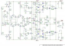
This schematics has now a common base input (VBE multiplier) for the CFP output stage.
However, I am still not assured of the potential cross conduction problem at high frequency as indicated by Kanwar. Any suggestions?
Hi
This schematics has now a common base input (VBE multiplier) for the CFP output stage.
However, I am still not assured of the potential cross conduction problem at high frequency as indicated by Kanwar. Any suggestions?
Attachments
Re: New revised version 0E30
thanks for new schematic, fab
.... you have many updated versions now ... maybe 7-8
I download and I will have a look
If we change our own idea, every time somebody have a different opinion
then we may lose our own idea.
Advice:
- listen to suggestions
- think if YOU want to do like that
- think if goes WITH your own idea
- then YOU decide what to change or not
In short:
Be true to Your Idea
while learn from other ideas
Your Idea will, sometime, be better or as good as other idea
lineup
fab said:Hi
This schematics has now
a common base input (VBE multiplier) for the CFP output stage.
thanks for new schematic, fab
.... you have many updated versions now ... maybe 7-8
I download and I will have a look
If we change our own idea, every time somebody have a different opinion
then we may lose our own idea.
Advice:
- listen to suggestions
- think if YOU want to do like that
- think if goes WITH your own idea
- then YOU decide what to change or not
In short:
Be true to Your Idea
while learn from other ideas
Your Idea will, sometime, be better or as good as other idea
lineuplineup said:
thanks for new schematic, fab
.... you have many updated versions now ... maybe 7-8
I download and I will have a look
If we change our own idea, every time somebody have a different opinion
then we may lose our own idea.
Advice:
- listen to suggestions
- think if YOU want to do like that
- think if goes WITH your own idea
- then YOU decide what to change or not
In short:
Be true to Your Idea
while learn from other ideas
Your Idea will, sometime, be better or as good as other idea
Thanks lineup for the reminder...
In fact I really have 30 versions now!!
All have some differences like no bootstrap caps but acive loading in input stage with regular VAS, etc....
I normally follow your above advices but I take seriously the advices where I am not sure... for example, from simulation I can not get similar transient slopes for rising and falling edge of the 10KHs Square wave without reducing a lot the slew rate...but maybe it is my transistor models that are not accurate enough...
So, at this point, I will have to take the decision about persuing this inverting lateral mosfet design (with the risk of instability difficulties or cross conduction problems...) thus I need some advices...
or
go back to usual lateral mosfet follower output stage...However, I would like to try something different with symetrical input stage with active loading and output error correction...
I ahev already built prototype with CFP in place of the buffer stage before the output stage but could not get satisfactorily response to 2u-8Ohms 10KHz square wave...so before I jump to prototype phase I need some assurance..
New model rev 3B
Hi
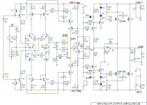
I did not "like" the bootstrap caps (electrolytics...) so I used a high input stage gain with active load instead. However, to do that I had to remove the buffer stage after input stage in previous version and use a traditional VAS (cascode) with "medium" open loop gain. The output impedane is now 10 times lower with this circuit version...
Playing with the caps value I could equalize more the rising and falling edge of the square wave (as shown with the simulator...)
Hi
I did not "like" the bootstrap caps (electrolytics...) so I used a high input stage gain with active load instead. However, to do that I had to remove the buffer stage after input stage in previous version and use a traditional VAS (cascode) with "medium" open loop gain. The output impedane is now 10 times lower with this circuit version...
Playing with the caps value I could equalize more the rising and falling edge of the square wave (as shown with the simulator...)
Attachments
Re: new model rev 3B
yes, looks very nice and flat
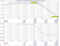
the open loop gain is not too high, + 56.7 dB: 650-700 maybe
fab said:AC analysis of OPEN LOOP circuit to show "flat" open loop medium gain until about 20 KHz (simulation).
yes, looks very nice and flat
the open loop gain is not too high, + 56.7 dB: 650-700 maybe
Hi lineup
yes I think that the relatively small open loo could suffice since I have fate in the linearity of the gain stages because of local degeneration...anyway just changing some resistor values and it is now 63db...
What do you think of this version 3B compared to previous model ...rev 30?
Thanks
yes I think that the relatively small open loo could suffice since I have fate in the linearity of the gain stages because of local degeneration...anyway just changing some resistor values and it is now 63db...
What do you think of this version 3B compared to previous model ...rev 30?
Thanks
I really can not tell much.
I wish I had the knowledge you have about this amplifier.
But this testing you show is promising.
When I said 'not too high gain', this was not anything negative.
If amplifier have good linearity in open loop
then we may need not too much feedback.
So having lower gain, still may give enough feedback
for very good closed loop performance.
If you now have 63dB.
And you have closed loop gain ~20, (= 26 dB )
This gives feedback ~37dB.
I have elsewhere told I, in some amplifiers, aim for 40dB feedback.
I know Pass and JLH have built amplfiers
having less feedback than this.
Very good amplifiers.
To print or view offline, download the PDF version - PLH_amplifierWeb source: http://www.passdiy.com/amps.htm
The PLH Amplifier: The classic JLH - Pass style
......................
My own approach is to make the signal path as simple as possible,
work to lower the distortion of that basic circuit before feedback is applied, and then apply minimal (or no) feedback,
largely in agreement with the comments in Linsley-Hood’s original article.
The result is not always the best objective measurements, but the sound is often interesting.
.
lineup
- Status
- This old topic is closed. If you want to reopen this topic, contact a moderator using the "Report Post" button.
- Home
- Amplifiers
- Solid State
- AMP with inverting output stage mosfet