I don't know if the holes line up, but it isn't difficult to make more. Just know whether you're tapping the hole (to bolt directly into), or if you're drilling all the way through and putting a nut on the back side (which I did, after buying the drills and taps for 3mm bolts).
I presume you mean this one: Deluxe 4U Aluminum – diyAudio Store
If you look in the Heatsink section, there's a link to their "universal mounting system" - clicking on it takes you to a page explaining some of the details. On it is a link to the PDF file with the actual measurements on it. Here's a direct link if that's too much work. 8) https://cdn.shopify.com/s/files/1/1006/5046/files/universal-mounting-specification-v2.1.pdf
As for a 4U case, that's probably overkill. I have a 24v power, R12 mod & R15 in a 2U case (300mm deep) and it runs cool enough to put my forearms on the fins for as long as I want, and only be mildly uncomfortable.
Your amp prbably run about 45 C on the heatsink.
With 24V and both R15 and R12 mods.....is that the 8W ACA?
Did you adjust the "bias" to 12.5V instead of 10V ?
No. The Universal Mounting System is not made for the ACA, as the ACA has always had it's own chassis.
The ACA chassis smaller as the thermal requirements are much, much smaller. A 4U 300mm would be appropriate for the most of the other Pass/Firstwatt designs.
The new version of the ACA (mainly a different PCB layout to fit a new chassis design) is being worked on now and will be available in the store hopefully by the end of March.
The 4U alluminium Deluxe chassis:
There are some pre-drilled holes in the heatsinks. Are the PCB for ACA made for the pre-drilled holes?
Thank you!
I will wait and see what you come up with at the end of March.
Then I will have components ready for the PSU.
I will wait and see what you come up with at the end of March.
Then I will have components ready for the PSU.
No. The Universal Mounting System is not made for the ACA, as the ACA has always had it's own chassis.
The ACA chassis smaller as the thermal requirements are much, much smaller. A 4U 300mm would be appropriate for the most of the other Pass/Firstwatt designs.
The new version of the ACA (mainly a different PCB layout to fit a new chassis design) is being worked on now and will be available in the store hopefully by the end of March.
Your amp prbably run about 45 C on the heatsink.
With 24V and both R15 and R12 mods.....is that the 8W ACA?
Did you adjust the "bias" to 12.5V instead of 10V ?
I built 24v-ish (c-r-cc as I despise switchers) with R12 / 15 mod and set it at whatever half the rail V is.
Heatsinks are 140 x 140 x 45, enclosed but well ventilated and I'd say it runs cosy.
Sounds great feeding 8 / 10 inch Tannoys or Eminence beta12lta in Planet10 box. In a 16 x 11 x 8ft room, same capabilities as el84pp A/B amp - slightly floppy bass but then it aint a bass heads amp
")
No. The Universal Mounting System is not made for the ACA, as the ACA has always had it's own chassis.
The ACA chassis smaller as the thermal requirements are much, much smaller. A 4U 300mm would be appropriate for the most of the other Pass/Firstwatt designs.
The new version of the ACA (mainly a different PCB layout to fit a new chassis design) is being worked on now and will be available in the store hopefully by the end of March.
I agree, it was not MADE for the ACA, but it has 3 different 40x80 mounting points, like the ACA I have, with mounts for the power devices that look to be in the same place (I relocated my power devices to center height at 25/75% down the length of my heat sink, so I can't measure the exact placement - but a few inches of wire wouldn't be the end of the world).
If I recall correctly, Papa said the "new ACA" will have a different name, so keep your eyes open for anything/everything.
Last edited:
I agree, it was not MADE for the ACA, but it has 3 different 40x80 mounting points, like the ACA I have, with mounts for the power devices that look to be in the same place (I relocated my power devices to center height at 25/75% down the length of my heat sink, so I can't measure the exact placement - but a few inches of wire wouldn't be the end of the world).
If I recall correctly, Papa said the "new ACA" will have a different name, so keep your eyes open for anything/everything.
So nobody knows (only "Papa") if the schematic has changed for the "new ACA"?
I assume that it will still be able to run at 24V and bias current will be 1 - 1.5 A ?
Who is "Papa"? ....Nelson Pass?
certainly issue for JLH thread somewhere else , but anyway
P2 is there to enable setting of modulation of upper output resistor , thus influencing THD spectra
it is also influencing DC level on output node (inner side of output cap) , so you need to set it (DC level) iteratively
if in doubt , just convert to original JLH schematic
P2 is there to enable setting of modulation of upper output resistor , thus influencing THD spectra
it is also influencing DC level on output node (inner side of output cap) , so you need to set it (DC level) iteratively
if in doubt , just convert to original JLH schematic
ACA Troubleshooting Help
Hello everyone.
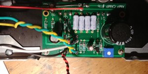
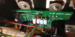
I finished my first ACA build and it sounded wonderful. I was really surprised at the build. This was my first build and it was an amazing experience.
I decided to clean up the wiring runs; to make it neat and tidy. You know that saying "if it ain't broke, you should totally mess with it - whats the worst that could happen"?
I finished the first board and tested it. The channel stopped working properly.
Initially, I was getting very very faint audio from the channel. Then, nothing. At all.
I have tested:
-checked rca cable
-checked speaker cable
-checked source out
-powerbrick is powered up
-adapter is wired properly in chasis
-power is running from the supply through the switch
-switch working properly
-power to the board at 24v
-led lights up
-however when I test q1 for voltage I get 0
-does not heat up
-I went back over all my soldering and re wired a second time
-other than the wiring I have not intentional changed anything
Pretty sure I ve managed to do something inadvertently and I am out of my depth to trouble shoot it further. I am a complete noob and as part of the learning process I'd love to figure this one out. Any insight/advice would be great.
Thanks in adavance
Hello everyone.
I finished my first ACA build and it sounded wonderful. I was really surprised at the build. This was my first build and it was an amazing experience.
I decided to clean up the wiring runs; to make it neat and tidy. You know that saying "if it ain't broke, you should totally mess with it - whats the worst that could happen"?
I finished the first board and tested it. The channel stopped working properly.
Initially, I was getting very very faint audio from the channel. Then, nothing. At all.
I have tested:
-checked rca cable
-checked speaker cable
-checked source out
-powerbrick is powered up
-adapter is wired properly in chasis
-power is running from the supply through the switch
-switch working properly
-power to the board at 24v
-led lights up
-however when I test q1 for voltage I get 0
-does not heat up
-I went back over all my soldering and re wired a second time
-other than the wiring I have not intentional changed anything
Pretty sure I ve managed to do something inadvertently and I am out of my depth to trouble shoot it further. I am a complete noob and as part of the learning process I'd love to figure this one out. Any insight/advice would be great.
Thanks in adavance
Attachments
no shorts on back side ?
everything properly soldered ?
Thanks for the quick reply.
Everything was working so I am assuming the parts are in the right place. Just pulled the board and while some of the solders are not exactly pretty, it looks to be short free...
Attachments
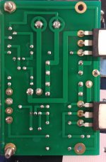
yeah ,short free and hopelessly cold , in most places
find proper video tutorial for soldering (not smd) , find some old pcb and do some exercising
It was my first soldering project. Learned lots along the way. Thank you for the advice. Would this cause the failure or is this more an aesthetic/best practice kind of thing. Would it be worth pulling the components and re soldering?
cold solder joint means no contact or bad contact (having resistance )
no need for pulling , use solder sucker pump to remove most of already applied solder , then solder again properly
again - best to prolong it few evenings , and practice soldering on some old pcb , they're everywhere
no need for pulling , use solder sucker pump to remove most of already applied solder , then solder again properly
again - best to prolong it few evenings , and practice soldering on some old pcb , they're everywhere
cold solder joint means no contact or bad contact (having resistance )
no need for pulling , use solder sucker pump to remove most of already applied solder , then solder again properly
again - best to prolong it few evenings , and practice soldering on some old pcb , they're everywhere
Thanks again, Ill keep you posted.
So nobody knows (only "Papa") if the schematic has changed for the "new ACA"?
I assume that it will still be able to run at 24V and bias current will be 1 - 1.5 A ?
Who is "Papa"? ....Nelson Pass?
The Schematic is essentially unchanged, the resistor mod has been included. The biggest differences are the layout to accommodate the new stereo chassis.
Yes, Papa is Nelson.
paceworldwide also has an excellent series of videos available on youtube, if you don't mind the dated style. #7 has good examples of correct and incorrect joints and what causes them. Thing is, every board is a bit different and sometimes you need adjust your technique a bit based on how things are behaving.
BK
- Home
- Amplifiers
- Pass Labs
- Amp Camp Amp - ACA