Ooooh, I've just been double checking that each side of each chip has power and ground and I think I have found it....

The 3.3v board print is sort of in between 2 holes. I've opted for the left one, but I'm now pretty sure it should be the one to the right...
Great!... Move to the right one and cross the fingers

Let me know
Regards,
Enrico
ok! much improved progress, but not quite there yet....
I've moved that connector 1 to the right and now my Pi recognises it has an output device properly and will initialise Squeezelite and play a track.
Unfortunately, it doesn't get as far as the DDDAC yet...
I get a light hum on the output of the dddac.
I've tested continuity between the output resistors of the S03 and the bck, rlck, data and gnd pins on my dddac mainboard, so I know that's all good.
Now I just have to track down where it's going missing in the middle...
Hi Enrico, James, and Palmito.
I was advised that high-clock frequency(greater then 90Mhz) has the tendency of higher "phase-noise".
With regards to DDDAC, I ponder the following;
1. Were there a benefit using 100Mhz vs something like 45/49.xxMhz?
2. Can DDDAC best work with 100Mhz while on specs it said system-clock is at 49.xxMhz for 192khz source/material?
3. For source beyond 192khz, specs does not specified the relevant system-clock speed. Assume the Dac chip does not have the capability beyond 192khz?
@James, I hope you get your S03 sorted! Mine is on its way, hopefully end of Oct.")
Many thanks,
Chanh
I was advised that high-clock frequency(greater then 90Mhz) has the tendency of higher "phase-noise".
With regards to DDDAC, I ponder the following;
1. Were there a benefit using 100Mhz vs something like 45/49.xxMhz?
2. Can DDDAC best work with 100Mhz while on specs it said system-clock is at 49.xxMhz for 192khz source/material?
3. For source beyond 192khz, specs does not specified the relevant system-clock speed. Assume the Dac chip does not have the capability beyond 192khz?
@James, I hope you get your S03 sorted! Mine is on its way, hopefully end of Oct.
Many thanks,
Chanh
Last edited:
Palmito.
I was advised that high-clock frequency(greater then 90Mhz) has the tendency of higher "phase-noise"
Hi Chanh. I wish I was more knowledgeable about this... but I'm not! Quote below is from post #976 , I probably misunderstood Acko and got the opposite idea, that given that the pcm1794 generates mck from bck, we should try to feed it the cleanest bck possible. We all know this would mean the lowest jitter, but Acko's suggestion is that the faster the clock rate the *lower* the phase noise:
3) On going with a higher than 100mhz clock rate xo, since Doede's dac doesn't use MCK so you are shooting for the lower jitter and pulse modulation error which would have an effect on BCK, which is used by the dac chip to generate MCK Acko commented:
There is of course nothing stopping you from going higher ( up to 600MHz for the Potsemi chips) to see if there are further benefits so long as low jitter XOs are chosen.
1) If I misunderstood Acko there is none, but if I understood him what I said above applies. My original clocks on the SO3 were SI590cd (98.304/90.3168). I replaced one of them for the lower jitter 100mhz chrystek (and disabled the other SI XO, so that only the 100mhz is feeding the dac) and I thought the sound quality improved (no blind tests, just extended listening). But I can't tell if the improvement came exclusively from the lower jitter clock, the slightly higher frequency or both.With regards to DDDAC, I ponder the following;
1. Were there a benefit using 100Mhz vs something like 45/49.xxMhz?
2. Can DDDAC best work with 100Mhz while on specs it said system-clock is at 49.xxMhz for 192khz source/material?
3. For source beyond 192khz, specs does not specified the relevant system-clock speed. Assume the Dac chip does not have the capability beyond 192khz?
2) ?
3) ?
Hi Enrico, James, and Palmito.
I was advised that high-clock frequency(greater then 90Mhz) has the tendency of higher "phase-noise".
With regards to DDDAC, I ponder the following;
1. Were there a benefit using 100Mhz vs something like 45/49.xxMhz?
2. Can DDDAC best work with 100Mhz while on specs it said system-clock is at 49.xxMhz for 192khz source/material?
3. For source beyond 192khz, specs does not specified the relevant system-clock speed. Assume the Dac chip does not have the capability beyond 192khz?
@James, I hope you get your S03 sorted! Mine is on its way, hopefully end of Oct.
Many thanks,
Chanh
Hi Chanh, I am afraid that I don't have a better answer than one palmito give you already to your good questions.
I can just say that my combo of rpi, S03 and DDDAC is playing really well, at least for my taste
Maybe Acko should highlight all of us about.
Regards,
Enrico
oooh, hold the bus!
I've been double checking all the connections and I didn't have the rck going to pin 3 on the top right potato chip...
So close now I can almost hear it!
Hi James,
Just curious, what about your S03? Is playing?
Many Thanks to Frankie and Enrico for your responses!
I am too not knowledgeable enough and my research were based on none-scholar sources as such Google!
Til date what I have learnt wrt S03 and Doede's DAC are as following;
1. For PCM1794 DAC, its Specifications defines a system-clock speed at 45.xxMHz for input sample frequency at 192kHz. No clock speed was specified for higher input sample frequency beyond 192kHz!?!. If my understanding is correct, the system-clock speed defined max at 45.xxMHz, higher frequency clock input may have concerns with jitters as the result of phase noise, pulse modulation, and most of all EMI due to higher (98/90.xx) switching frequencies stress on the board, components, power consumption. Please don't quote me on this?
2. I also read from another thread(the new and very expensive clock) that an audiophile in Japanese posted his feedbacks on 90/98.xx clocks have made the sound a little more edginess/less-musical than the 45/49.xx of the same clock maker (NDK). Nonetheless, I also read from Iancanada, the author of FIFO....., said he found using 90/98.xx to be better, however, the 90/98.xx were a better grade than those of 45/49.xx.
Based on these findings, I am confused. Perhaps Acko can share his thoughts on this very special subject of his?
Btw, rumour says Acko might coming out a "SuperCape" for BBB! This SuperCape also has UPS with lithium upto 1hr after power shortages, and also has all the I2S/DSD switching capability like the Botic Cape? If the Rumor is true, I definitely be interested and put my name down for it. May be Acko could clarify this Rumor for group buying?
Best,
Chanh
Not yet it seems....Hi James,
Just curious, what about your S03? Is playing?
I spotted 3 soldering errors that I made and each time I was sure I'd cracked it!
But still no output :'(
I need a very thorough check once more that each chip is getting power and gnd, clock signal and data as intended in the schematic before I start to wonder if the components are definitely ok.
@dwjames: Hi James - I can see that you are getting help from emyeuoi which has the S03 as well so will just comment briefly .. In case your last "check & change" doesn't work what I meant by checking the data lines is that (if you have an oscilloscope going to a 100 MHz?) you should be able to follow the XOs output to the flip-flops and now that the Pi outputs a signal also to the flip-flops. If acko has included a schematic for your SO3 there should be an indication as to where the XO output enters the flip-flops, and also where the BCK, LRCK and DATA lines come from the pi. If you can check these (and eventually also the output from the flip-flops) you may be able to see what may be amiss ... BTW if I'm not mistaken pin 3 on the XO is the output so what you see measuring with a multimeter is an averaged DC value of your XO going up and down 100.000.000 times/ second ;-)
Good luck in finding the solution!
Jesper
P.S.:
Good luck in finding the solution!
Jesper
P.S.:
It is typically so that halving the oscillator frequency reduces phase noise by 6 dBs.1. Were there a benefit using 100Mhz vs something like 45/49.xxMhz?
Thanks@dwjames: Hi James - I can see that you are getting help from emyeuoi which has the S03 as well so will just comment briefly .. In case your last "check & change" doesn't work what I meant by checking the data lines is that (if you have an oscilloscope going to a 100 MHz?) you should be able to follow the XOs output to the flip-flops and now that the Pi outputs a signal also to the flip-flops. If acko has included a schematic for your SO3 there should be an indication as to where the XO output enters the flip-flops, and also where the BCK, LRCK and DATA lines come from the pi. If you can check these (and eventually also the output from the flip-flops) you may be able to see what may be amiss ... BTW if I'm not mistaken pin 3 on the XO is the output so what you see measuring with a multimeter is an averaged DC value of your XO going up and down 100.000.000 times/ second ;-)
Good luck in finding the solution!
Jesper
P.S.: It is typically so that halving the oscillator frequency reduces phase noise by 6 dBs.
I have a very simple scope, which only goes to 100Khz which isn't perfect, but I guess it will be enough to detect, compare and trace the signals
Thanks
I have a very simple scope, which only goes to 100Khz which isn't perfect, but I guess it will be enough to detect, compare and trace the signals
Hi James, I am sorry to read that you still can't make the S03 to play... I think that you can just troubleshoot the board like gentlevoice suggest you... good luck!
Enrico
Hi Chanh. I wish I was more knowledgeable about this... but I'm not! Quote below is from post #976 , I probably misunderstood Acko and got the opposite idea, that given that the pcm1794 generates mck from bck, we should try to feed it the cleanest bck possible. We all know this would mean the lowest jitter, but Acko's suggestion is that the faster the clock rate the *lower* the phase noise:
3) On going with a higher than 100mhz clock rate xo, since Doede's dac doesn't use MCK so you are shooting for the lower jitter and pulse modulation error which would have an effect on BCK, which is used by the dac chip to generate MCK Acko commented:
There is of course nothing stopping you from going higher ( up to 600MHz for the Potsemi chips) to see if there are further benefits so long as low jitter XOs are chosen.
1) If I misunderstood Acko there is none, but if I understood him what I said above applies. My original clocks on the SO3 were SI590cd (98.304/90.3168). I replaced one of them for the lower jitter 100mhz chrystek (and disabled the other SI XO, so that only the 100mhz is feeding the dac) and I thought the sound quality improved (no blind tests, just extended listening). But I can't tell if the improvement came exclusively from the lower jitter clock, the slightly higher frequency or both.
2) ?
3) ?
I am assuming this arrangement is with the RPi that does not take external clock. So after isolation ASync re-clocking is the only option and as I have indicated this will introduce 'pulse modulation" errors. But this get reduced at higher re-clocking frequencies. I believe Palmito has already experimented with 50MHz clocks and 100MHz clocks and reported improvement in SQ at 100Mhz - so this proves the point. Theoretically further improvement with even higher clock frequencies so long as phase noise is comparably low - otherwise it will negate the benefits above
Yes, BCK signals become the MCK for DDDAC or simlar DACs but BCK is referenced to the main clock used on the S03 so its jitter performance is obviously dependent on this Clock. So again you will need to pay attention to the phase noise of the clocks used. Re: results from Palmito, changing Si590 to CCHD950-100MHz improved the sound because CCHD950 has lower phase noise than Si590. The 98.304MHz to 100MHz is not too much (I think) for this contribution
@dwjames: In case you haven't yet solved your issues might I suggest that you connect the raspberry's BCK etc. directly to the DDDAC to find out if something goes out of the raspberry. If it plays connected like this the next step could be to connect the raspberry wires just before the flip-flops and then check if there's now music. If there is the XO and the flip-flops should be working...
Best regards,
Jesper
Best regards,
Jesper
Thanks
I have a very simple scope, which only goes to 100Khz which isn't perfect, but I guess it will be enough to detect, compare and trace the signals
You can also use a multimeter and measure the dc output of the signals.
With switching between Hi-Lo of a 3.3V system you should get an average 1.65V reading if perfect rail-rail swing @50% duty cycle. Allowing for tolerance, anywhere between 1.5V to 1.7V indicates healthy operation. I use this technique all the time for production testing and troubleshooting, saves the hassle of dragging a scope into place.
Start with the power supplies and see if devices are all getting 3.3V
Then check the Clock as this is the controlling signal for the rest
Last edited:
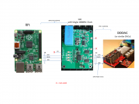
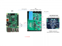
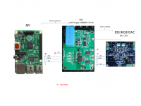
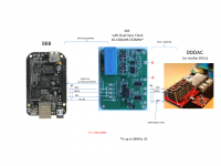
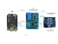
RPi-DDDAC Explained
Async w.r.t to RPi but Full Sync drive of DDDAC
I am assuming this arrangement is with the RPi that does not take external clock. So after isolation ASync re-clocking is the only option and as I have indicated this will introduce 'pulse modulation" errors. But this get reduced at higher re-clocking frequencies. I believe Palmito has already experimented with 50MHz clocks and 100MHz clocks and reported improvement in SQ at 100Mhz - so this proves the point. Theoretically further improvement with even higher clock frequencies so long as phase noise is comparably low - otherwise it will negate the benefits above
Yes, BCK signals become the MCK for DDDAC or simlar DACs but BCK is referenced to the main clock used on the S03 so its jitter performance is obviously dependent on this Clock. So again you will need to pay attention to the phase noise of the clocks used. Re: results from Palmito, changing Si590 to CCHD950-100MHz improved the sound because CCHD950 has lower phase noise than Si590. The 98.304MHz to 100MHz is not too much (I think) for this contribution
Async w.r.t to RPi but Full Sync drive of DDDAC
Attachments
- Status
- This old topic is closed. If you want to reopen this topic, contact a moderator using the "Report Post" button.
- Home
- Group Buys
- Amanero Isolator/Reclocker GB