S03 & BBB via Miero's Botic for both 44.1k & 48k family
I was hoping if someone or perhaps Acko could please advise whether this fully 2 clocks essembled S03 works with BBB via Miero's Botic driver for all 44.1 - 192k? i.e no Botic Cape is required and S03 is acting as external clock for 44.1k and 48k family when setting external clocks via Botic driver?
I am keen picking one up but if it doesn't work...?
Cheers.
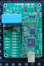
Hi Guys,Initial batch has arrived- 98.304MHz/90.3168MHz. Mounts in position X2
Doing some tests now. shipping soon...
I was hoping if someone or perhaps Acko could please advise whether this fully 2 clocks essembled S03 works with BBB via Miero's Botic driver for all 44.1 - 192k? i.e no Botic Cape is required and S03 is acting as external clock for 44.1k and 48k family when setting external clocks via Botic driver?
I am keen picking one up but if it doesn't work...?
Cheers.
Hi Guys,
I was hoping if someone or perhaps Acko could please advise whether this fully 2 clocks essembled S03 works with BBB via Miero's Botic driver for all 44.1 - 192k? i.e no Botic Cape is required and S03 is acting as external clock for 44.1k and 48k family when setting external clocks via Botic driver?
I am keen picking one up but if it doesn't work...?
Cheers.
It will work with BBB/Miero Botic drivers. Yet to try it myself but I do not see any technical issues. See post here for connections: ->S03-BBB
Test Results
Miksi,
Have you resolved this?
I am tracking a few issues posted here... some DAC or setup related, others a bit surprising but ...
I have done some tests using the AKU384 which is a special build based on the S03 and Amanero underpinnings.
Using JPlay5(Mini-bare bones version) on Win7 with ASIO or Kernel Streaming for native files up to 192KHz. No native 352k or 384k material so I used HQPlayer to upsample 44.k to stream at 384k for the high Fs tests.
DAC system is AKD12P (9018) clocked by the AKU384 in 'Turbo" Sync mode
Here are the results:
1. DAC was able to lock at lowest DPLL BW all the way up to 384KHz. Sounds really great! Very stable, no dropouts, noise, crackles or other issues.
2. Still early stages but I seemed to like JPlay combo with all the settings for buffer adjustments etc. JPlay loads entire file from disc to RAM and steadies the audio stream so the possible reason for a more palpable effect. But some settings can upset the system with noise and crackles, full reboot needed- so yes, player can affect playback if not properly setup
3. Sync mode brings out the best with all the micro details.
Haven't tried DSD yet or tweaked with zero DPLL BW. Letting it burn in a bit more and will post results later
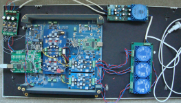
Hardware and prototype test bed as shown (any bids?") ). Looks like a maze (mess) and unsafe but signals are carefully routed and I am pleased with the results!
). Looks like a maze (mess) and unsafe but signals are carefully routed and I am pleased with the results!
I wasn't sure where to post this but because it involves Acko recklocker here it is.
After Win7 new, clean installation I wanted to test some behavior of different CPLD and CPU firmwares. In ConfigTool, pin 11 is set for 24.576 MHz selector.
First, I've flashed slave_for_1080 CPLD and 1080 CPU firmware. Only 384 KHz sample rate doesn't produce any sound, but 352 KHz gave me some really bad crackling and noise. I didn't expected it because it appeared after the played file and it quite scared me so I had to mute the amp and then only Arta was used as spectrum analyzer. I didn't try DSD files.
After this, slave2244 CPLD was flashed. In this case 352 KHz doesn't produce any signal on output and after 384KHz sample noise appears again. I must mention noise starts sometimes several minutes after file played. I used foobar in ASIO and kernel streaming mode, it doesn't matter. If I play file again its normally reproduced but noise is here again after few minutes. If any other sample rate is used (44.1, 48,..,192) there's no such problems.
With CPLD_for_1080 and cpu firmware 1080 plays all sample rates but with 352 and 384 we have noise after file is played.
Bitclk CPLD and CPU firmwares doesn't play 352 and 384 sample rates.
Miksi,
Have you resolved this?
I am tracking a few issues posted here... some DAC or setup related, others a bit surprising but ...
I have done some tests using the AKU384 which is a special build based on the S03 and Amanero underpinnings.
Using JPlay5(Mini-bare bones version) on Win7 with ASIO or Kernel Streaming for native files up to 192KHz. No native 352k or 384k material so I used HQPlayer to upsample 44.k to stream at 384k for the high Fs tests.
DAC system is AKD12P (9018) clocked by the AKU384 in 'Turbo" Sync mode
Here are the results:
1. DAC was able to lock at lowest DPLL BW all the way up to 384KHz. Sounds really great! Very stable, no dropouts, noise, crackles or other issues.
2. Still early stages but I seemed to like JPlay combo with all the settings for buffer adjustments etc. JPlay loads entire file from disc to RAM and steadies the audio stream so the possible reason for a more palpable effect. But some settings can upset the system with noise and crackles, full reboot needed- so yes, player can affect playback if not properly setup
3. Sync mode brings out the best with all the micro details.
Haven't tried DSD yet or tweaked with zero DPLL BW. Letting it burn in a bit more and will post results later
Hardware and prototype test bed as shown (any bids?
). Looks like a maze (mess) and unsafe but signals are carefully routed and I am pleased with the results!Attachments
Miksi,
Have you resolved this?
I am tracking a few issues posted here... some DAC or setup related, others a bit surprising but ...
I have done some tests using the AKU384 which is a special build based on the S03 and Amanero underpinnings.
Using JPlay5(Mini-bare bones version) on Win7 with ASIO or Kernel Streaming for native files up to 192KHz. No native 352k or 384k material so I used HQPlayer to upsample 44.k to stream at 384k for the high Fs tests.
DAC system is AKD12P (9018) clocked by the AKU384 in 'Turbo" Sync mode
Here are the results:
1. DAC was able to lock at lowest DPLL BW all the way up to 384KHz. Sounds really great! Very stable, no dropouts, noise, crackles or other issues.
2. Still early stages but I seemed to like JPlay combo with all the settings for buffer adjustments etc. JPlay loads entire file from disc to RAM and steadies the audio stream so the possible reason for a more palpable effect. But some settings can upset the system with noise and crackles, full reboot needed- so yes, player can affect playback if not properly setup
3. Sync mode brings out the best with all the micro details.
Haven't tried DSD yet or tweaked with zero DPLL BW. Letting it burn in a bit more and will post results later
Hardware and prototype test bed as shown (any bids?
Hello Acko,
First, there is no problem with playing any of the sample rates on lowest DPLL BW, no crackling or dropouts. The noise appears after playing music 352.8k and 384k but not immediately, some 30sec to 2min, it's never the same time, and remains until next play.
Eh, I still didn't check data lines during the noise but if it's clean there is something wrong with the DAC chip itself.
Anyway everything is good while music plays.
Second, only usable combination of firmwares is CPLD_for_1080 and firmware_1080. This works for any sample rate. Now I see new firmware fw_1082_USB10e with description "PB19 pin66 when 1=HS20 when 0=FS10".
Maybe Domenico should enlighten us about new "stuff" a little bit.
Regards
PS. I still waiting for AKX-9890NDK shipped on 16.9.
...
Second, only usable combination of firmwares is CPLD_for_1080 and firmware_1080. This works for any sample rate. Now I see new firmware fw_1082_USB10e with description "PB19 pin66 when 1=HS20 when 0=FS10".
Maybe Domenico should enlighten us about new "stuff" a little bit.
Regards
PS. I still waiting for AKX-9890NDK shipped on 16.9.
Thanks Miksi, I did further tests and found HQPlayer is not really stable and produces its own slight 'hash' noise when upsampling. Not audible when music playing but makes it a bit fluffy and noise remains even after music stopped. Had to go close to speakers to hear it and needed full reboot to clear. JPlay is really clean so I really need to test with native 384 or 352 files to validate. Where did you get yours or are able to share yours for tests?
Regarding the Combo384, you should use Slave_for_1080 and firmware_1080 as per Amanero's advice with this S03 setup. Then from Configbits tab set:
Prescaler: MCLK/1
Word length: 32
Stream format: I2S
Slave Mode (MCLK Input): select
Pin1: 22.579MHz
Pin11: 24.576MHz
Ignore all other options.
Didn't work for me with the CPLD_for_1080 firmware. Somehow 44.1k based played. No sound for 48k so it is not the right setup and confirmed by Amanero as this makes the unit use the internal clock and will mess with the S03 clock input to it!
In touch with Dom on the issues. Can't seem to fault the Combo384 or other devices in the chain.Output signals appear healthy on my system.
Will test further and advise.
Please wait for another week or so for the shipment. More samples on the way ~2wks and will cover you in case of any delivery issues
Last edited:
Finally making USB music!
BK
BK
An externally hosted image should be here but it was not working when we last tested it.

Yes, I think that one of the local oscillators remained turned on regardless of synchronous mode but I can't remember exactly which firmware was involved. Both local XO select lines should be set to low in the synchronous enabled firmware, for less disturbance.
I will try again Slave_for_1080, but as far as I remember I couldn't get every sample rate to work with it.
I've generated 352 and 384 files in the software, tried also upsampling during playpack and always get noise after playback...
I will try again Slave_for_1080, but as far as I remember I couldn't get every sample rate to work with it.
I've generated 352 and 384 files in the software, tried also upsampling during playpack and always get noise after playback...
Found a nice cheap USB chassis mount solution. The right angle connection really helped out. It's amazing how long the straight ones really are, and I didn't leave quite enough room with my layout.
Seems to be working fine, but I noticed that the metal housings on the two ends of the cable are not connected. I checked some of my other USB cables and some had continuity and some did not. Presumably this would impact the shielding. Not sure if either end is connected to the braided shield.
What's the best type for this application?
BK
An externally hosted image should be here but it was not working when we last tested it.
An externally hosted image should be here but it was not working when we last tested it.
Last edited:
Hi,
could someone sanity check my work please?
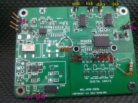
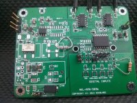
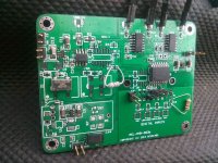
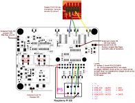
I have an S03 board, with a single 100mhz clock, to go inbetween a Raspberry Pi and a DDDAC 1974.
In the labelled picture, pink is for a 5v power supply, red goes to the Pi and Yellow goes to the DDDAC. Orange is to explain the extra resistors that I added in and didn't have smd ones. Now I look at the pictures, R3 doesn't seem to be doing a lot....
I was using the information from this post:
http://www.diyaudio.com/forums/group-buys/227502-amanero-isolator-reclocker-gb-98.html#post3916986
combined with the 'Isolated Connection with Re-clocking - ASYNC mode' instructions.
If I put this between my Pi and DDDAC, I get nothing. The Pi doesn't see the DDDAC. I'm clearly missing something, maybe a jumper or a component I need to run this way?
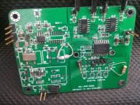
Please excuse the horrid soldering. It's ugly, but as far as I can tell, everything's connected properly....
thanks guys,
James
could someone sanity check my work please?
I have an S03 board, with a single 100mhz clock, to go inbetween a Raspberry Pi and a DDDAC 1974.
In the labelled picture, pink is for a 5v power supply, red goes to the Pi and Yellow goes to the DDDAC. Orange is to explain the extra resistors that I added in and didn't have smd ones. Now I look at the pictures, R3 doesn't seem to be doing a lot....
I was using the information from this post:
http://www.diyaudio.com/forums/group-buys/227502-amanero-isolator-reclocker-gb-98.html#post3916986
combined with the 'Isolated Connection with Re-clocking - ASYNC mode' instructions.
If I put this between my Pi and DDDAC, I get nothing. The Pi doesn't see the DDDAC. I'm clearly missing something, maybe a jumper or a component I need to run this way?
Please excuse the horrid soldering. It's ugly, but as far as I can tell, everything's connected properly....
thanks guys,
James
Attachments
Last edited:
Hi,
could someone sanity check my work please?
I have an S03 board, with a single 100mhz clock, to go inbetween a Raspberry Pi and a DDDAC 1974.
In the labelled picture, pink is for a 5v power supply, red goes to the Pi and Yellow goes to the DDDAC. Orange is to explain the extra resistors that I added in and didn't have smd ones. Now I look at the pictures, R3 doesn't seem to be doing a lot....
I was using the information from this post:
http://www.diyaudio.com/forums/group-buys/227502-amanero-isolator-reclocker-gb-98.html#post3916986
combined with the 'Isolated Connection with Re-clocking - ASYNC mode' instructions.
If I put this between my Pi and DDDAC, I get nothing. The Pi doesn't see the DDDAC. I'm clearly missing something, maybe a jumper or a component I need to run this way?
Please excuse the horrid soldering. It's ugly, but as far as I can tell, everything's connected properly....
thanks guys,
James
Hi James,
you have the same configuration of mine S03 with rpi and the DDDAC.
I will give a look carefully to your pictures but I can quickly say you that the 2 resistors not SMD (R3 and R18) are not needed. I will let you know if I can see anything else from your pics.
What about the grounds? You have more than one Vin... maybe you miss some gnd connection?
Regards,
Enrico
Hi James,
I actually have a DDDAC inspired DAC up and running with Acko Isolator board (and a custom made clock board) and it works quite fine. I understand that the SO3 is an integrated unit of the Amanero USB & Acko's XO board + isolator board. My setup works just fine except for the clicks between tracks that apparently is due to the Amanero board.
What I first notice is that you don't have a GND wire between the S03 and the DDDAC ... I would use some close to each of the data wires.
I'd also check the voltages on the S03 board to see if everything is as it should be.
Third, if it still doesn't play, I would try to track the data stream from the Pi towards the DDDAC with an oscilloscope. So as to see where there's no longer a signal.
Best regards,
Jesper
Thanks Enrico,Hi James,
you have the same configuration of mine S03 with rpi and the DDDAC.
I will give a look carefully to your pictures but I can quickly say you that the 2 resistors not SMD (R3 and R18) are not needed. I will let you know if I can see anything else from your pics.
What about the grounds? You have more than one Vin... maybe you miss some gnd connection?
Regards,
Enrico
I added the resistors when I was looking for some reason it wasn't working.
With the grounds, I have gnd to my Pi and to my dddac, but I only included 1 gnd to the power supply as I noted that J1, J2, J3, J6 GND are all connected via the ground plane of the board
Thanks Jesper,Hi James,
I actually have a DDDAC inspired DAC up and running with Acko Isolator board (and a custom made clock board) and it works quite fine. I understand that the SO3 is an integrated unit of the Amanero USB & Acko's XO board + isolator board. My setup works just fine except for the clicks between tracks that apparently is due to the Amanero board.
What I first notice is that you don't have a GND wire between the S03 and the DDDAC ... I would use some close to each of the data wires.
I'd also check the voltages on the S03 board to see if everything is as it should be.
Third, if it still doesn't play, I would try to track the data stream from the Pi towards the DDDAC with an oscilloscope. So as to see where there's no longer a signal.
Best regards,
Jesper
I do have a GND to the DDDAC, If you look at the left one of the top connectors, I have joined it to the outer pad of the ufl connector, not the inner, so it gets a gnd connection
I'll have a check for voltages. Are there obvious places to check without risking bridging chip contacts and blowing stuff?
Data stream's a funny one I think as my Pi won't contemplate playing anything unless it can see the dac, so I wouldn't be sure how to go about that one...
thanks,
James
Hi James,
looking in the pics that you send I can't see any missing parts or jumpers and the connections are correct.
I suppose that you check all the various Vin including the 3,3V from the rPI ?
Can you check what you can read from the out of the XO (pin 2)?
If you back in this thread you will found my posts for the same problem with my S03 at the first trial.
After all the troubleshooting with Acko we discover that was the XO
Regards,
Enrico
I understood the R18 10k resistor was to force that only X1 is present?Hi James,
looking in the pics that you send I can't see any missing parts or jumpers and the connections are correct.
I suppose that you check all the various Vin including the 3,3V from the rPI ?
Can you check what you can read from the out of the XO (pin 2)?
If you back in this thread you will found my posts for the same problem with my S03 at the first trial.
After all the troubleshooting with Acko we discover that was the XO
Regards,
Enrico
As far as I can tell from the XO, I have:
Pin1 EN - not connected. goes to Q1 which is not present
pin2 GND - GND
Pin3 ck - 2.93v DC
Pin4 vcc - 3.3v DC
I understood the R18 10k resistor was to force that only X1 is present?
As far as I can tell from the XO, I have:
Pin1 EN - not connected. goes to Q1 which is not present
pin2 GND - GND
Pin3 ck - 2.93v DC
Pin4 vcc - 3.3v DC
In my understanding the CKSEL circuit with U8, the R18 and the Q2 is required for the Amanero. You correctly don't install the U8 and the relevant Q2 so there is no reason to install the R18.
About the XO pins, I just measured mine that is playing now and I have 1,66V at the pin 3.
I am sorry but I think that you need to dismount (carefully) the XO and test it separately from the circuit to be sure that is working properly. If I remember correctly you should read half of the Vin (more or less 1,6V)
I will be happy to help you making others values cross check if you wish.
Maybe Acko have much better suggestion than mine?
Cool, thanks.In my understanding the CKSEL circuit with U8, the R18 and the Q2 is required for the Amanero. You correctly don't install the U8 and the relevant Q2 so there is no reason to install the R18.
About the XO pins, I just measured mine that is playing now and I have 1,66V at the pin 3.
I am sorry but I think that you need to dismount (carefully) the XO and test it separately from the circuit to be sure that is working properly. If I remember correctly you should read half of the Vin (more or less 1,6V)
I will be happy to help you making others values cross check if you wish.
Maybe Acko have much better suggestion than mine?
I just checked again and thankfully I'm actually getting 1.58v at pin 3.
I'm not sure how I measured that wrong by probing the X1 output pin directly
but I got a clean measurement from the pin3 pad for X2, which is directly connected.thanks,
James
Cool, thanks.
I just checked again and thankfully I'm actually getting 1.58v at pin 3.
I'm not sure how I measured that wrong by probing the X1 output pin directly
thanks,
James
Great! Your XO looks ok
I can't see well from the pics... you check already that you don't have any bridges between the pins of the flipflop or others IC?

- Status
- This old topic is closed. If you want to reopen this topic, contact a moderator using the "Report Post" button.
- Home
- Group Buys
- Amanero Isolator/Reclocker GB