Hi Bob,
I am using 1% Dales and hope they are within spec. I did put my scope probes over r23/r25 earlier this evening and the waveforms match perfectly so I'm confident the diff pair is good. I'm not so sure about the output devices so I might try matching those again. I did change feedback resistors r16/r30 from 100k to 200k in order to increase the input sensitivity but the asymmetry issue existed before this change. I'll check r18/r28 input resistors to see that I've not inadvertently put 100k in there by mistake....
And thanks for responding.
Hi Jason,
I remember having the same issue when I was looking for a way to connect a subwoofer to my Aleph-X´s. I haven´t found a solution to use one output alone because it always looked distorted.
If you look at the balanced signal (summ of both) this looks very nice and is what your speaker sees. So in the end I connected the sub in another way and didn´t think about it anymore.
William
Hi William,
"Another suggestion was to raise the value of the "Macmillan" resistors (mine were 4.7K so I increased them to 10k) - that has made no difference to the relative amplitudes (but has affected the output waveform, was a sinewave, now a sinewave with a dip at the top (looks like an M) instead of peaking properly"
The two output waveforms look correct (different amplitutde but both clean sine waves), it's only the sum of the outputs that looks like an M. Was Ok before increasing the Macmillan resistors to 10k.
I worked late last night and couldn't get to my test bench, but i'll have a go at resetting the trimmers to see if that helps.
** Bob - I thought about the input resistors a bit more - if they were incorrect then the waveforms over the source resistors on the diff pair (r23/r25) would be uneven but they are perfectly matched, so I don't think it's that.
Jason
Hi Jason,
it is quite a long time ago since I looked at these. McMillans are 33k at the moment (with JFet inputs and a PTC in the current source for the diff pair). Abs. DC starts at 1 or 2V and stays around 0 after a while.
I also have a dip in the output but only at higher Frequencies (above 10kHz) and high voltages (over 24V rms) so very near clipping. It get´s worse in 4 Ohms.
I also tried matching the McMillans to 0,01% (at least when cold) which did help.
I will see if I can find my notes on this.
William
PS I did raise the McMillans because I think they are not good for sound quality. Going from 4k7 to 10k (with 9610 as input Fets) made quite a difference. Going any higher was not possible at that time because of absolute DC and some missing knowledge. There must be a thread on the dips too.
Last edited:
I have swapped a couple of the output FETs over and re-adjusted the trimmers. The output waveform is back to being a sine again but the non-symmetrical amplitude still prevails (and the relative offset has increased from 80 to 230mv.
I measured the gate voltages - the lower FETs have just over 12v on them, the current sources have about 5v on them.
I'll go back and try matching the output FETs again.
I measured the gate voltages - the lower FETs have just over 12v on them, the current sources have about 5v on them.
I'll go back and try matching the output FETs again.
OK - I have had the soldering iron and scope out and started playing again.
I added a 200 ohm trimmer in series with R25 and adjusted until I had matching amplitude on the two halves of the circuit. Adjusting the trimmer either matches the amplitude or trims the relative offset to zero but not both. Can anyone offer any advice on how to get this better for both?
I replaced R24 with a pair of KTY81/110 in parallel mounted to the Q1 heatsink with superglue - the pair didn't do the trick but adding a third pretty much did. I might try adding a 2k trimmer to the third PTC to see if I can get it any better (it seems to drift +/- 100mv).
I realised that I do still have the M in the sine wave (from the sum of the outputs), however if I invert the second channel on the scope everything comes back to how it should be - Can changing the Macmillans cause phase shift?
Jason
Hi Jason,
I´ve used one 10R trimmer as source resistors for the input (JFet) pair to set the relative dc offset (equalize the current). You could combine this with the trimmer on one drain resistor.
I´ve only used one PTC but changed the resistors (R24/R26) quite a lot and have only half of the bias current. 100mV Absolute is very good I think.
william
Taming the beast
OK Soldering iron out again and more tweaking.
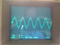
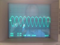
I have 10K trimmers over R23 and R25 - I can trim out most of the relative DC offset (20mv remaining) but still have issues with differences in the amplitude (and shape) of the waveforms on the outputs, also the two output waveforms don't cross over at the middle - I expected that they would (and should). I can adjust these factors a little by adjusting the 10K's over the top of R23/R25 but what you see on the scope traces is the best I have achieved so far.
If I invert channel 2 then the output looks like a clean sine wave, without the inversion it looks like a lower amplitude "M" - I can't recall when that came about - might have been when I increased the value of the McMillan resistors - I might have to go to back to a lower value (currently 20K).
The absolute DC offset is proving difficult to tame - after warming up it seems to sit around a sweet spot for some time and then wanders off without any good reason, I am therefore reluctant to attach a speaker to the outputs (currently just 6.6 ohms of power resistor). I would be grateful for any further advice.
OK Soldering iron out again and more tweaking.
I have 10K trimmers over R23 and R25 - I can trim out most of the relative DC offset (20mv remaining) but still have issues with differences in the amplitude (and shape) of the waveforms on the outputs, also the two output waveforms don't cross over at the middle - I expected that they would (and should). I can adjust these factors a little by adjusting the 10K's over the top of R23/R25 but what you see on the scope traces is the best I have achieved so far.
If I invert channel 2 then the output looks like a clean sine wave, without the inversion it looks like a lower amplitude "M" - I can't recall when that came about - might have been when I increased the value of the McMillan resistors - I might have to go to back to a lower value (currently 20K).
The absolute DC offset is proving difficult to tame - after warming up it seems to sit around a sweet spot for some time and then wanders off without any good reason, I am therefore reluctant to attach a speaker to the outputs (currently just 6.6 ohms of power resistor). I would be grateful for any further advice.
Attachments
and don´t worry about absolute DC offset, your speakers won´t see it!
As I see you are measuring near clipping level? Try something near 1 or 2V to start with.
And have a look at the current limiters on the negative halves, it could be that they are already working (Q4, Q9 and resistors 10,13,35,39. Maybe you have to change those to change the limit.
As I see you are measuring near clipping level? Try something near 1 or 2V to start with.
And have a look at the current limiters on the negative halves, it could be that they are already working (Q4, Q9 and resistors 10,13,35,39. Maybe you have to change those to change the limit.
Last edited:
Hello
I would like to ask some opinion about the Aleph X to be replaced by the UGS power amp.
I don't know if someone already done it.
Do it worth the investment, the extra job etc.
I do have the Aleph X and I love it , also I planed to mode the front end to J Fet.
Now I really don't know do I stick with the Aleph X just mode the front end and enjoy it or it worth the investment to change it to the UGS ad some extra power mosfet and bias the hell out of it.
About the UGS I read someone compared with the Aleph J and the J performed way better.
Any advise welcome.
Greetings
Hi William,
"and don´t worry about absolute DC offset, your speakers won´t see it!" - If it were a few millivolts I wouldn't worry - problem was that it was creeping up to 14v or so. I appreciate that the speaker won't see it but it doesn't leave much headroom for the circuit to work as an amplifier. I've since swapped a few things around - McMillans back down to 10k and changed the way I trim out the relative DC offset on the diff pair. I now have just a few millivolts relative offset and absolute offset drifts +/- 100mv (but is usually less and now doesn't drift skyward). Things are looking much more like they should. I plan to run it for a while and confirm that it continues to behave and then start putting the speaker protection together (wanted to start that a while ago). I'm still not sure about that output inversion issue on one channel that I mentioned previously, to my mind inverting the scope channel should not be needed ....
"and don´t worry about absolute DC offset, your speakers won´t see it!" - If it were a few millivolts I wouldn't worry - problem was that it was creeping up to 14v or so. I appreciate that the speaker won't see it but it doesn't leave much headroom for the circuit to work as an amplifier. I've since swapped a few things around - McMillans back down to 10k and changed the way I trim out the relative DC offset on the diff pair. I now have just a few millivolts relative offset and absolute offset drifts +/- 100mv (but is usually less and now doesn't drift skyward). Things are looking much more like they should. I plan to run it for a while and confirm that it continues to behave and then start putting the speaker protection together (wanted to start that a while ago). I'm still not sure about that output inversion issue on one channel that I mentioned previously, to my mind inverting the scope channel should not be needed ....
Does your scope have a Vert Diff position? A-B? Ch1-Ch2? Connecting scope probe Gnd to your Gnd will be fine. Your measurement will be between two Channels of the scope. 1 Channel will be inverted in typical operation.
I always have the Gnd lifted on my scope AC input but that is not something I'd recommend.
I always have the Gnd lifted on my scope AC input but that is not something I'd recommend.
Last edited:
Hi flg,
I have dual channels and channels 1 & 2 are both grounded to the central grounding point with one scope probe on each output. I expect one output to be swinging negative whilst the other swings positive, the sum ( ie channels 1 & 2 combined) should be a nice healthy sine wave but instead I see a wobbly m wave as the output. If I invert one of the channels then the resulting waveform is the large bridged sine wave output that I expected in the first place. I just don't understand why I need to invert one scope channel in order to see it how it should be.
I have dual channels and channels 1 & 2 are both grounded to the central grounding point with one scope probe on each output. I expect one output to be swinging negative whilst the other swings positive, the sum ( ie channels 1 & 2 combined) should be a nice healthy sine wave but instead I see a wobbly m wave as the output. If I invert one of the channels then the resulting waveform is the large bridged sine wave output that I expected in the first place. I just don't understand why I need to invert one scope channel in order to see it how it should be.
- Home
- Amplifiers
- Pass Labs
- Aleph-X builder's thread.