use xformer , if you ask me - by Brave Mickey recipe
take proven one , meaning especially on proven secondary loading , to have it linear 20-20K
take proven one , meaning especially on proven secondary loading , to have it linear 20-20K
If I have C1 shorted it`s ok to connect the amp balanced?
Leave C1 in place and connect it balanced.
Hello 6L6 and nice to see you again!
I'll give it a try tomorrow and report back cause now I've put in charge the 3x 12v 30amp(each) lipos that power up my dac and iv stage and this takes a while...
So tomorrow will try with c1 in the circuit but with ground connected only on the amp side.
I'll give it a try tomorrow and report back cause now I've put in charge the 3x 12v 30amp(each) lipos that power up my dac and iv stage and this takes a while...
So tomorrow will try with c1 in the circuit but with ground connected only on the amp side.
Hello Papa
Refering to your Aleph J schematic, R27 is connected directly to the gate of Q5 and Q6.
Is it possible that R27 is intended to be connected between the junction of R25, R26 and C2? If connected this way it results in 2A bias and seems to operate somewhat better into low impedance loads (from memory).
The way you have it connected results in approximately 2.6A of static bias (a little high).
I know the issue of high bias was addressed by members with trimpots, but it was applied somewhat differently.
It seems to me R27 should have been connected between R25, R26, and C2

I was meant to ask this question approximately 8 years ago. Back then I was a scaredy cat.
Refering to your Aleph J schematic, R27 is connected directly to the gate of Q5 and Q6.
Is it possible that R27 is intended to be connected between the junction of R25, R26 and C2? If connected this way it results in 2A bias and seems to operate somewhat better into low impedance loads (from memory).
The way you have it connected results in approximately 2.6A of static bias (a little high).
I know the issue of high bias was addressed by members with trimpots, but it was applied somewhat differently.
It seems to me R27 should have been connected between R25, R26, and C2
I was meant to ask this question approximately 8 years ago. Back then I was a scaredy cat.
Last edited:

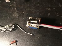
I have built some 2 terminal ccs's to bias the ltp of my each j.
I am using r8 in series with the ccs, from positive first I have r8 then the ccs.
I have instaled the ccs in one channel, set it up for 14 ma bias for the ltp and is all working up and biasing correctly.
Does r8 position(first or after ccs) and value matter?
Having 14v drop acros r8 I am considering to lower its value to 500ohm. Is this recommended?
Attachments
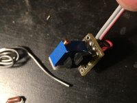
I have replaced the original ccs with a 2 terminal ccs so I am not using anymore c4,z1,q2 and r5, the ccs is connected in place of ce pins of ztx550. Now the ltp bias is similar to ba1 front end only that I use something else as ccs insted of k170.
I have reworked also the second channel
I have reworked also the second channel
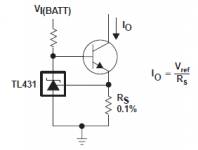
Something like this
So you are using Rs around 180 Ohms? Or trimpot there?
- Home
- Amplifiers
- Pass Labs
- Aleph J Schematic