As Zen Mod suggested make this fixed resistor no smaller than 150 Ohms then a 200 Ohm trimpot in series would work well.
Probably better solution is just make Rs a fixed resistor between 160 and 250 Ohms.
Then use trimpot at drain of jfet to adjust dc offset of amp.
Probably better solution is just make Rs a fixed resistor between 160 and 250 Ohms.
Then use trimpot at drain of jfet to adjust dc offset of amp.
Last edited:
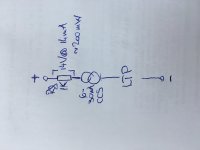
The 1k resistor reduces the voltage drop/power dissipation on the jfet ccs (ie BA1 CCS), it also is a handy location to confirm/measure current through jfet ccs. But you are not using the JFET CCS.
Provided you aren't exceeding the power dissipation of bjt then you may not need it as you have a resistor at the emitter to confirm/measure current. 500 Ohms would be ok though. It will depend on the bjt used and it's power rating, either way keeping it under 200mW is probably a good idea.
You still need an appropriate resistor to feed current into TL431. What are you using there?
Last edited:
Just a suggestion.
Going from Papa's Aleph J circuit, he recommends 8.3mA for the CCS. So using a fixed resistor value of 300 Ohms for Rs will get you that, you don't need a trimpot unless you want to deviate away from Papa's design choice.
I suppose it depends on how critical Papa thinks a value of 1k at the drain of the jfet is.
I personally wouldn't lose sleep over deviating away from this value by plus or minus 10%.
Last edited:
I am running 1.6a on each output fet so for this the higher front end bias.
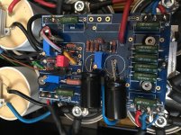
I prefer to keep the pots for two reasons.
First is that I can change bias on the fly. Since in the winter room temp is colder I can exaggerate a little bit with the output stage bias") There were summer days when I didn't power on the amps because the room temp was too high.
There were summer days when I didn't power on the amps because the room temp was too high.
With 1.6a bias on each fet I get 35-40c above room temp on each heatsink.
And second is that I can trim perfectly everything to get a low output dc offset.
To adjust offset and bias of outputstage I have installed trimpots with series resistors in place of r7 and r27.
I prefer to keep the pots for two reasons.
First is that I can change bias on the fly. Since in the winter room temp is colder I can exaggerate a little bit with the output stage bias
There were summer days when I didn't power on the amps because the room temp was too high.With 1.6a bias on each fet I get 35-40c above room temp on each heatsink.
And second is that I can trim perfectly everything to get a low output dc offset.
To adjust offset and bias of outputstage I have installed trimpots with series resistors in place of r7 and r27.
Attachments
I have increased the bias to 1.7a on each output fet and I am thinking to remove r27 at least to compare the sound...
My speakers have the minimum impedance at 190hz(3.4r). Quite impressed...
You can remove R27 but you will not get much more curent. Its just Vbe of ZTX 450 divided by 0,47.
For more output current you need to rise up AC current gain ( reduce R24 from 1k2 to less then 1k, but not to much then became unstable) and current protection divider r13/r14 should be adjusted to not clip.
My example has 52% Ac gain with 910 ohms on the R24 position.
For my taste it was best setup, bias was 2.6 A.
Generally as you increase the gain of the current source the total distortion
goes down, but the content of higher order harmonics goes up. As you
go below 50%, you decrease the maximum output current. Personally I
prefer the sound somewhat less than 50%, and with SIT devices less yet,
all the way to 0% (constant current source).
goes down, but the content of higher order harmonics goes up. As you
go below 50%, you decrease the maximum output current. Personally I
prefer the sound somewhat less than 50%, and with SIT devices less yet,
all the way to 0% (constant current source).
Aleph J with VFETs ?
First of all if you wish to ask me a technical question, please kindly ask at the forum.
I wish to reserve my PM for my own private communications with friends.
The question was whether I would have a schematics for an Aleph J for Sony VFETs.
The simple answer is no.
I have no VFETs myself, nor do I have any intension to own any.
But AFAIK, they are depletion devices.
So you can bias them in the same way as e.g. a LU1014.
See :
Aleph J Schematic
Aleph J Schematic
This is just to give you an idea how it can be done.
You'll have to work out the details according to your own needs.
Cheers,
Patrick
well, you can blame me for fact that non-friends are bugging you through PM

some Greedy Boyz asked me how to use LU in Aleph J, and I told them that you had solution long ago , and that is somewhere in Aleph J related threads .....
though, I did save it now, so no more ..... bugging
some Greedy Boyz asked me how to use LU in Aleph J, and I told them that you had solution long ago , and that is somewhere in Aleph J related threads .....
though, I did save it now, so no more ..... bugging
Bugging is OK. But why so secretive ?
Just ask here.
I also need to use the search function.
I am sure you also can.
See also :
FirstWatt J2
Cheers,
Patrick
Just ask here.
I also need to use the search function.
I am sure you also can.
See also :
FirstWatt J2
Cheers,
Patrick
Bugging is OK. But why so secretive ?
Just ask here.
....
human nature, what else .......
some are probably thinking that asking in thread is not of enough importance to others ( and it is, always)
some are just reluctant to show in public ignorance about something
regarding that, being recognized Dummy in public is confirmed as most effective way of getting all answers
I'm getting them all, all the time
- Home
- Amplifiers
- Pass Labs
- Aleph J Schematic