My 0Vs are both floating - ie not tied to Mains GND (Earth).
The chassis is EARTHED obviously for safety but at no point are either 0V connected to chassis. The Pre-amp is the same.
Dear Andy5112405,
You might want to follow a simple "PASS" rule
") to wire your GNDs to Earth (Chassis) each through a power thermistor (like CL_60) or at least a power resistor, 10R /3W or so, if you don't have a thermistor handy. This provides a safety path for wrong currents in case there is a failure in the amplifier.
to wire your GNDs to Earth (Chassis) each through a power thermistor (like CL_60) or at least a power resistor, 10R /3W or so, if you don't have a thermistor handy. This provides a safety path for wrong currents in case there is a failure in the amplifier. You can do the same in your pre-amp, btw
It never hurts to have extra-protection. You might want to add some DC protect boards to your finished amp, in order to protect the speakers in case of DC at the outputs.
Congrats on your build, and have a safe finish,
Cheers,
nAr
Dear Andy5112405,
You might want to follow a simple "PASS" rule
You can do the same in your pre-amp, btw
It never hurts to have extra-protection. You might want to add some DC protect boards to your finished amp, in order to protect the speakers in case of DC at the outputs.
Congrats on your build, and have a safe finish,
Cheers,
nAr
Any suggestions for these DC protection circuits? I'm wanting them for my F-5. I should probably look at CanAmman's build, I think I remember him using them....
Russellc
a little off_topic but :
The design seen in UP (UGS Power) seems to work nicely
http://psykok.homelinux.org/diy/UP/UPSchemas.pdf
page 3 , it is said to be a copy / adapted to differential of a Velleman kit ...
nAr
The design seen in UP (UGS Power) seems to work nicely
http://psykok.homelinux.org/diy/UP/UPSchemas.pdf
page 3 , it is said to be a copy / adapted to differential of a Velleman kit ...
nAr
Last edited:
Help with thermodynamics
Thermodynamics isn't one of my specialisations.
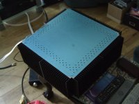
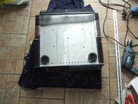
Can someone please look at the two photos.
The top of the case has a matix of 4.5mm holes drilled above the MOS-FETs to let the heat escape.
At the moment I have 3mm holes drilled in the bottom of the case to let cool air in.
How big should the holes in the bottom be ? Obviously there is no danger of little fingers dropping things through the bottom like there is at the top.
The spacing of the holes will allow 10mm holes, hopefully that will allow enough air convection for interior cooling.
The amp runs cool enough with its lid removed so it's only interior heat that has to be removed once the lid is in place.
The lid has now been painted matt black to match the heatsinks.
Thermodynamics isn't one of my specialisations.
Can someone please look at the two photos.
The top of the case has a matix of 4.5mm holes drilled above the MOS-FETs to let the heat escape.
At the moment I have 3mm holes drilled in the bottom of the case to let cool air in.
How big should the holes in the bottom be ? Obviously there is no danger of little fingers dropping things through the bottom like there is at the top.
The spacing of the holes will allow 10mm holes, hopefully that will allow enough air convection for interior cooling.
The amp runs cool enough with its lid removed so it's only interior heat that has to be removed once the lid is in place.
The lid has now been painted matt black to match the heatsinks.
Attachments
Thermodynamics isn't one of my specialisations.
Can someone please look at the two photos.
The top of the case has a matix of 4.5mm holes drilled above the MOS-FETs to let the heat escape.
At the moment I have 3mm holes drilled in the bottom of the case to let cool air in.
How big should the holes in the bottom be ? Obviously there is no danger of little fingers dropping things through the bottom like there is at the top.
The spacing of the holes will allow 10mm holes, hopefully that will allow enough air convection for interior cooling.
The amp runs cool enough with its lid removed so it's only interior heat that has to be removed once the lid is in place.
The lid has now been painted matt black to match the heatsinks.
No need to be an expert in thermodynamics. The higher number of holes, the closest you will be from the no-lid figure in T°C.
Therefore I would drill all holes @ 10 mm, and add all possible holes on the lid extending towards center. I would also try to get more holes dia.10 mm on the bottom metal sheet too.
Best,
nAr
I would also try to get more holes dia.10 mm on the bottom metal sheet too.
nAr
Never mentioned to drill in the center of the bottom sheet, that's pretty obvious. Just more in the circumference
nAr
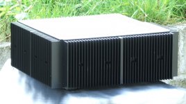
It's coming along.
It's had its final coat of paint now.
The bottom now looks like a colander, so hopefully the internal heat will be convected through the holes in the lid.
At #245 the holes were only along one edge and were only 4mm. They now go all the way around the circumference of the bottom and are 9.5mm.
Obviously it now has four feet as well.
Attachments
Last edited:
How big should the holes be ?
Makes zero difference for these diameters with natural air flow, all that counts is the total hole area.
Big holes always have the advantage of more area/airflow for the same diameter total and having to drill fewer.
Fan : Use an internal fan running slowly and check inside ambient air temp. 35°C is a max if you want to hold the capacitor bank long life. For the speed, your mileage may vary. Try & Error is also part of DIY's routines
Chokes : Yes, better "air core" 200% 1 - 2 mH should be sufficient in a CLCC filter dimensioned as yours. The more wire, the more inductant; but internal R also rises, so gives stronger dissipation factor, extra heat, and you loose some V+/V-olts inside.
Resistors : That should prevent any ground "damage", they could also achieve quieter operation. Anyway, it provides an audio ground connection without creating a ground loop, at least
Happy diy,
nAr
Chokes : Yes, better "air core" 200%
1 - 2 mH should be sufficient in a CLCC filter dimensioned as yours. The more wire, the more inductant; but internal R also rises, so gives stronger dissipation factor, extra heat, and you loose some V+/V-olts inside.Resistors : That should prevent any ground "damage", they could also achieve quieter operation. Anyway, it provides an audio ground connection without creating a ground loop, at least
Happy diy,
nAr
- Status
- This old topic is closed. If you want to reopen this topic, contact a moderator using the "Report Post" button.
- Home
- Amplifiers
- Pass Labs
- Aleph 4 Strickly DIY Project Build