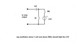
I don't know which problem you have , especially if you can't see any oscillation ;
anyway - good trick for detecting oscillation is written here : http://www.diyaudio.com/forums/soli...r-high-end-audio-equipment-4.html#post1384373
I told you befoore that best way for implementing attenuator is on input side of Pumpkin ; not because of itself , but because of amp side - that way it sees output impedance of attenuator , not of , which is made to drive anything ....
anyway - good trick for detecting oscillation is written here : http://www.diyaudio.com/forums/soli...r-high-end-audio-equipment-4.html#post1384373
I told you befoore that best way for implementing attenuator is on input side of Pumpkin ; not because of
itself , but because of amp side - that way it sees output impedance of attenuator , not of , which is made to drive anything ....BEAUTIFUL MUSIC.
No TURN ON THUMP, No TURN OFF THUMP.
ABSOLUTE SILENCE with no input.
At HALF POWER I'm seeing +/- 40mV dips on the PSU rails.
After half an hour the half heatsink on the rear has reached a scorching 36 degrees C.
All I need to do now is fit the other channel - I can't wait.
It's a cool day in the UK today, only 20 degrees, but still heat does not seem to be too much of a problem. The six MOS-FETs on each "Leg" are biassed at 400mA each, 2.4A per Channel.
PSU rails are +/- 42V
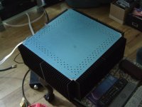
Just to re-iterate, this is the Aleph 4
")
I've noticed that there is no sign of a Zobel Network on the diagrams that I am using. Is this intentional or are vital components missing ?
Well my Elna Simic IIs have arrived. I'm just about to change C11, the Tantallum cap.
I've also got nylon bolts for the chokes.
At the same time I'm going to add a low value (4.7uF) polypropolene across each supply rail at the input of the amps.
Still wondering why the transformers get v.warm, but only occasionally. I don't think my trusted Tektronics 468 has the bandwidth to show UHF oscillations.
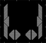
Time to see if I've drilled enough holes in the lid.
A good trick here is to make a template rather than rely on all your holes lining up. I bought one of those steel plates that DIY builders merchnats sell fro joining two bits of timber together (cost me £2.00).
A good trick here is to make a template rather than rely on all your holes lining up. I bought one of those steel plates that DIY builders merchnats sell fro joining two bits of timber together (cost me £2.00).
Attachments
....................
Attachments
I've drilled 4.5mm holes to stop little fingers dropping little things into the amp.
I'm not a thermodynamisist. Are the holes big enough or should they be bigger.
There is very little space on the base plate for holes so most of the heat must be radiant rather than convected.
I'm not a thermodynamisist. Are the holes big enough or should they be bigger.
There is very little space on the base plate for holes so most of the heat must be radiant rather than convected.
I've drilled 4.5mm holes to stop little fingers dropping little things into the amp.
I'm not a thermodynamisist. Are the holes big enough or should they be bigger.
There is very little space on the base plate for holes so most of the heat must be radiant rather than convected.
I never go over 3 mm. To danger...
See the deck sketch for my N. Pass F5.
Attachments
What an absolute Pain-in-the-**** that was, changing the tantalum C11 for the Elna Simic II.
I had to remove the two mains transformers and the chokes just to get at the PCBs.
While I'm in the process of changing C11 on both channels I'll sort out ventillation holes in the bottom of the chassis and fit the chokes with nylon bolts.
One question comes to mind.
With the transformers stacked on top of each other - does the primary phasing make any difference ?
Attachments
.....
With the transformers stacked on top of each other - does the primary phasing make any difference ?
nope
It can make a difference in the residual voltage between GND and earth, when not tied together. Ideally one wants this voltage to be the lowest possible before link GND to earth with a power R or a thermistor. So primary phasing can make a difference. The lowest the V, the better for the sound, said "warmer" and less "sibilant".
When using xformers with real "balanced" primary windings, like some RCore models, the residual voltage is very low and changing the primary phasing doesn't make anymore difference
Ideally, I assume you want your 2 xformers to be wired the same way.
Best,
nAr
When using xformers with real "balanced" primary windings, like some RCore models, the residual voltage is very low and changing the primary phasing doesn't make anymore difference
Ideally, I assume you want your 2 xformers to be wired the same way.
Best,
nAr
It can make a difference in the residual voltage between GND and earth, when not tied together. Ideally one wants this voltage to be the lowest possible before link GND to earth with a power R or a thermistor. So primary phasing can make a difference. The lowest the V, the better for the sound, said "warmer" and less "sibilant".
When using xformers with real "balanced" primary windings, like some RCore models, the residual voltage is very low and changing the primary phasing doesn't make anymore difference
Ideally, I assume you want your 2 xformers to be wired the same way.
Best,
nAr
As the transformers aren't identical I'll try to measure the magnetic field direction from each of the primaries.
You reckon this could be causing my sibilance ? No-one else has considered that possibility.
As the transformers aren't identical I'll try to measure the magnetic field direction from each of the primaries.
You reckon this could be causing my sibilance ? No-one else has considered that possibility.
Sibilance can have other causes, for example a slight oscilation in the highs, can lead to some non-linearities in the bandwidth. Sometimes oscilation doesn't break the whole amplifier ... Amp doesn't oscilate on purely resistive load. But does on some non linear impedances as speakers. Your mileage may vary
If you can do it, I suggest you use a scope at the output, and input some sine from 50Hz to 200kHz, and see how they look; if not possible, compare Output Voltage between 50Hz tone and 10 KHz tone on a dummy load @ 1W, amplitudes must be equal
Hope this helps,
nAr
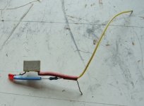
Going back to the transformers initially.
I'm at a bit of a loss as to how to work out the phasing of the transformer cores.
Initially I placed a compass in the centre of each toroid and applied a DC voltage (low voltage) to the primary winding. In both cases I can get the compass to turn in the same direction.
Am I on the right track ??
I'm at a bit of a loss as to how to work out the phasing of the transformer cores.
Initially I placed a compass in the centre of each toroid and applied a DC voltage (low voltage) to the primary winding. In both cases I can get the compass to turn in the same direction.
Am I on the right track ??
Sibilance can have other causes, for example a slight oscilation in the highs, can lead to some non-linearities in the bandwidth. Sometimes oscilation doesn't break the whole amplifier ... Amp doesn't oscilate on purely resistive load. But does on some non linear impedances as speakers. Your mileage may vary
If you can do it, I suggest you use a scope at the output, and input some sine from 50Hz to 200kHz, and see how they look; if not possible, compare Output Voltage between 50Hz tone and 10 KHz tone on a dummy load @ 1W, amplitudes must be equal
Hope this helps,
nAr
I've had scope with input at 60kHz and sine wave is as clean as a whistle. Square wave is not so pretty though - see previous threads.
Hello,
I wouldn't use a compass
Just run your amp, channel by channel, with GND untied from earth. Then measure the V between GND and earth. Power down and reverse primary. Power on, then measure again. "Good" wiring is lowest read value. Then do the same for the other channel ... Ultimately, don't forget to connect GND of each channel to earth via thermistor CL60. That's all ...
Best,
nAr
- Status
- This old topic is closed. If you want to reopen this topic, contact a moderator using the "Report Post" button.
- Home
- Amplifiers
- Pass Labs
- Aleph 4 Strickly DIY Project Build