Mark, referring to the circuit diagram, I have followed your recommendations. C11 is a Tantallum SMD capacitor (normally chosen because tantallum doesn't mind continuous operation at low voltage). C4 and C7 are Silvered Mica, C7 (C1 on circuit) is MKPS Polyethelylen MKPS4. C8 and C9 are nothing special but low ESR Panasonic 220uF/35V.
All resistors are vishay R55 1%, with the exception of the Source resistors which are 1% 3W Metal Oxide.
All MOS-FETs were matched, in groups, to within 1% of each other.
All resistors are vishay R55 1%, with the exception of the Source resistors which are 1% 3W Metal Oxide.
All MOS-FETs were matched, in groups, to within 1% of each other.
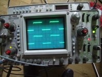
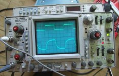
The oscilloscope is quite revealing.
At 1kHz and 10KHz things aren't too bad. At 60KHz things are starting to go wrong.
OK my signal source is not perfect, but could this be the problem ?
These are boards made using Mark's design ???
In all traces, the upper trace is the input and the lower trace is the output with the speakers connected.
Attachments
With plastic or even nonmagnetic screws, maybe with PVC binding belts,...How else would you suggest mounting them.
But, first of all, I would make a try with inductance measure (with and without metal screw), or, at least, to make an audible test.
No further ideas...

Again, congrats to your work!
 & for fun!
Please don't run 60kHz SW into your speakers ...
We don't expect a SW at 60kHz, the design uses the FET capacitance etc to gently roll-off the upper end - especially when this sees the load of the speakers.
What you see looks normal. (to me!)
Have you tried listening R<>L mono ... are both channels identical?
Random failure/misadventure is highly unlikely to be duplicated exactly in both channels.
Cheers
Mark
With plastic or even nonmagnetic screws, maybe with PVC binding belts,...
But, first of all, I would make a try with inductance measure (with and without metal screw), or, at least, to make an audible test.
No further ideas...
Again, congrats to your work!
I'll try removing them altogether to start with. The diagrams that I have been following simply use CCC smoothing. This will also increase rail voltage closer to the recommended +/-48V
OK. I've borrowed a decent Sig Gen from work.
The results aren't too much different from those obtained yesterday.
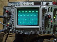
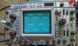
Pic1 is Right Ch at 500mV and 50KHz.
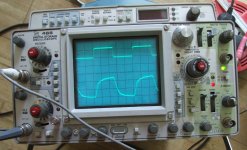
Pic2 is Right Ch at 500mV and 100KHx
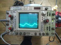
Pic3 is Left Ch at 500mV and 100KHz
Top trace is 500mV input - bottom trace is output (no speakers attached).
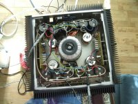
I have removed the Chokes from the PSU leaving 100000uF CCC per rail - 4 rails in total.
The TSSSSS is present on both channels.
There are three 220uF caps in the Aleph 4. C8 and C9 are in the current source and C11 is on the -ve INPUT.
Mark Finnis recommended a tantalum for C11. I'm starting to think these may be the cause of the trouble. I am using the amp unbalanced.
The results aren't too much different from those obtained yesterday.
Pic1 is Right Ch at 500mV and 50KHz.
Pic2 is Right Ch at 500mV and 100KHx
Pic3 is Left Ch at 500mV and 100KHz
Top trace is 500mV input - bottom trace is output (no speakers attached).
I have removed the Chokes from the PSU leaving 100000uF CCC per rail - 4 rails in total.
The TSSSSS is present on both channels.
There are three 220uF caps in the Aleph 4. C8 and C9 are in the current source and C11 is on the -ve INPUT.
Mark Finnis recommended a tantalum for C11. I'm starting to think these may be the cause of the trouble. I am using the amp unbalanced.
Attachments
I use pumpkin with Aleph 2 monoblocks and nothing is overheating and oscillating. In your case, I'd draw detailed schematics of ground connections and try to find out if there are any currents running through grounding wires between preamp and power amp. Also check if there are any ground loops and draw grounding connections in both Aleph and Pumpkin/Shunty channels. If you have different levels of ground potential between Aleph and Pumpkin it could cause the situation that some current is running through grounds causing problems you face.
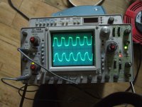
I'll let the pictures speak for themselves.
Channel 1 is CLCC
Channel 2 is CCC
Both are set up identically on the 'scope.
There is a clear ripple on the CCC which is completely absent on the CLCC.
Wether or not this is audible is still debateable.
Channel 1 is CLCC
Channel 2 is CCC
Both are set up identically on the 'scope.
There is a clear ripple on the CCC which is completely absent on the CLCC.
Wether or not this is audible is still debateable.
Attachments
- Status
- This old topic is closed. If you want to reopen this topic, contact a moderator using the "Report Post" button.
- Home
- Amplifiers
- Pass Labs
- Aleph 4 Strickly DIY Project Build