Quote>I'm knackered. Cutting 10mm Alluminium Plate by hand is hard work.
For straight cuts Forghet the hand saw and the Jig saw much faster and accurate with an angle grinder and metal cutting disk.
You could get the 1 mm thick ones and the 4 1/2 in grinder can be bought for £20 £30.
Just let the disk do the work keeping light passes against a straight edge there is a knak to it less force and more patience is the secret.
I built the Vauxall plant with it (well my share of it)
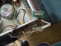
On the caps what do you use to mesure them my meter gives up at 10mU
I've got both. Unfortunately the jigsaw holds the blade by friction, which isn't strong enough when cutting alluminium.
I did use the angle grinder in the end.
33000uf caps that measure nearly 300% their rating consistently? are you sure your meter just cant measure such a huge value properly?
I measured them using a resistor and a constant voltage, using a stopwatch to see how long they took to charge.
My method was just to match them and make sure they were OK as they were NOS. Obviously there was room for error. I was surprised.
If they are NOS they will need to be reformed for several hours at full voltage with current limiting resistors to be able to use them or you could have a spectacular malfunction when you hit the switch. At the least they will blow a fuse.
Thanks for the good advice but these have been in operation in my A700 for nearly a year now. The A700 is being stripped for bits that can be used in the Aleph 4. As the thread says, this is a build on a shoestring budget.
Well, I'm going to try CLCC as a first stab.
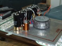
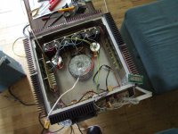
One of the Power Supplies has been tested, the next step is marrying it up with the amplifier.
The second Toroid is going to sit on top of the first with its components mirrored onto the spare space that you can see.
Its all going to be quite a tight fit.
One of the Power Supplies has been tested, the next step is marrying it up with the amplifier.
The second Toroid is going to sit on top of the first with its components mirrored onto the spare space that you can see.
Its all going to be quite a tight fit.
Attachments
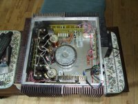
arent those chokes pretty close to the amp boards? i thought chokes were really quite bad when it comes to em spray? what brand are they btw? i've been looking for a reasonably priced unit to try out in my fet circlotron psu and since you are doing it on a budget perhaps yours fit the bill?
As the chokes are after the first of the caps there shouldn't be too much EM spray, they will be largely working at smoothed DC.
I bought them from a UK supplier that specialses in L/S Crossovers. Four of them cost me about £40 GBP, so not cheap. It's not too difficult to source 22mH chokes that can handle 10A. I chose Air-Cored to prevent saturation problems, hence their size.
I bought them from a UK supplier that specialses in L/S Crossovers. Four of them cost me about £40 GBP, so not cheap. It's not too difficult to source 22mH chokes that can handle 10A. I chose Air-Cored to prevent saturation problems, hence their size.
I'm having problems mounting the amplifier boards so I may just remove the chokes altogether.
TBPH they made no difference to the sound of the A700. The Aleph 4 is more powerful but 12 x 33000uF should be enough to keep it quiet.
The chokes I sourced were simply coils of wire with no mounting arrangements at all. The simplest way of mounting them was to mount them upright with a bolt through their centres.
Last edited:
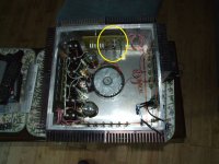
After a rethink, I resited the amplifier boards so that they are now mounted on the heatsinks with 25mm spacers.
Do you think the chokes will give me any problems with EM spray ?
The only components near the chokes are the output resistors, the main amplifier circuitry is shown within the yellow ring.
Do you think the chokes will give me any problems with EM spray ?
The only components near the chokes are the output resistors, the main amplifier circuitry is shown within the yellow ring.
Attachments
All is cooking nicely.
One half is now built and has been powered up.
Bias currents are as expected 400mA per MOS-FET.
DC Output Offset is about 20-30mV which isn't too bad.
Next step is to see if it will produce music.
The weather has been against me to get the second Power Supply finished, one step at a time I say.
One half is now built and has been powered up.
Bias currents are as expected 400mA per MOS-FET.
DC Output Offset is about 20-30mV which isn't too bad.
Next step is to see if it will produce music.
The weather has been against me to get the second Power Supply finished, one step at a time I say.
After a half hour soak test, the back bank of MOS-FETs with only one heatsink, as opposed to two for the others, is atill only at 45 degrees, it is hot to the touch but I can keep my fingers there for ten seconds.
It looks as though the fan will not be necessary after all.
It looks as though the fan will not be necessary after all.
BEAUTIFUL MUSIC.
No TURN ON THUMP, No TURN OFF THUMP.
ABSOLUTE SILENCE with no input.
At HALF POWER I'm seeing +/- 40mV dips on the PSU rails.
After half an hour the half heatsink on the rear has reached a scorching 36 degrees C.
All I need to do now is fit the other channel - I can't wait.
It's a cool day in the UK today, only 20 degrees, but still heat does not seem to be too much of a problem. The six MOS-FETs on each "Leg" are biassed at 400mA each, 2.4A per Channel.
PSU rails are +/- 42V
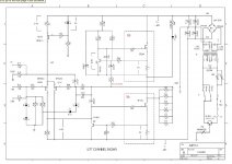
Just to re-iterate, this is the Aleph 4
")
No TURN ON THUMP, No TURN OFF THUMP.
ABSOLUTE SILENCE with no input.
At HALF POWER I'm seeing +/- 40mV dips on the PSU rails.
After half an hour the half heatsink on the rear has reached a scorching 36 degrees C.
All I need to do now is fit the other channel - I can't wait.
It's a cool day in the UK today, only 20 degrees, but still heat does not seem to be too much of a problem. The six MOS-FETs on each "Leg" are biassed at 400mA each, 2.4A per Channel.
PSU rails are +/- 42V
Just to re-iterate, this is the Aleph 4
Attachments
Last edited:
- Status
- This old topic is closed. If you want to reopen this topic, contact a moderator using the "Report Post" button.
- Home
- Amplifiers
- Pass Labs
- Aleph 4 Strickly DIY Project Build