XRK how do you get good pressure for mosfet to cooler ? Also better have the coolers running at max speed befor powering up the ampboard, I think temp will stabilize around 45 degrees above ambient, but I seem to be only one that sees over 200W dissipation per mosfet and 6A bias")
Need to use an L channel aluminum bar across the MOSFET. That’s what the two holes across the frame, perpendicular to the mosfet pins are for.
The CPU cooler frame does not have a lot of metal to mount extra threaded holes, but I am checking the flex and stiffness of the board/CPU cooler combo and I think the single L bracket with two holes should not have any problem applying enough pressure to make a good thermal contact. Those clips do a surprisingly good job of holding on. To be even more sturdy, simply changing the plastic clips for 4 x 8-32 bolts/nuts will do a great job of holding it all in place.
So I need to assemble the +/-35v CRC PSU with the new 400VA trafos. Need a big plank of wood to put both amps on (dual mono) so I can hook up to speakers once it works.
I may need to go buy more aluminum L bracket stock.
So I need to assemble the +/-35v CRC PSU with the new 400VA trafos. Need a big plank of wood to put both amps on (dual mono) so I can hook up to speakers once it works.
I may need to go buy more aluminum L bracket stock.
I’m setting up my linear 400VA 25v trafo and am getting strange result. The dual secondaries are producing 27.66vac and 27.65vac. I connect them to my Project16/Prasi CRC PSU with MUR880 diodes and 4x22mF (35v) caps and I get +/-33.6vdc.
1.41x26.65vac should make 37.4v. This is no load. I tried it with a different trafo (same 400VA and 25V) and even different PSU’s - still same 33.6vdc. Line voltage is 126vac. I double checked the phase of the windings and al looks good.
1.41x26.65vac should make 37.4v. This is no load. I tried it with a different trafo (same 400VA and 25V) and even different PSU’s - still same 33.6vdc. Line voltage is 126vac. I double checked the phase of the windings and al looks good.
I’m setting up my linear 400VA 25v trafo and am getting strange result. The dual secondaries are producing 27.66vac and 27.65vac. I connect them to my Project16/Prasi CRC PSU with MUR880 diodes and 4x22mF (35v) caps and I get +/-33.6vdc.
1.41x26.65vac should make 37.4v. This is no load. I tried it with a different trafo (same 400VA and 25V) and even different PSU’s - still same 33.6vdc. Line voltage is 126vac. I double checked the phase of the windings and al looks good.
Hi X,
you are very near to the voltage rating of cap and might even exceed with 27VAC secondaries.
regards
Prasi
Hi X,
you are very near to the voltage rating of cap and might even exceed with 27VAC secondaries.
regards
Prasi
Good point, Prasi, I was hoping under load it would sag a bit to 24v and I would be ok. Maybe need to upgrade to 50v caps.
ALPHA BB CPU Cooler Mounting Details
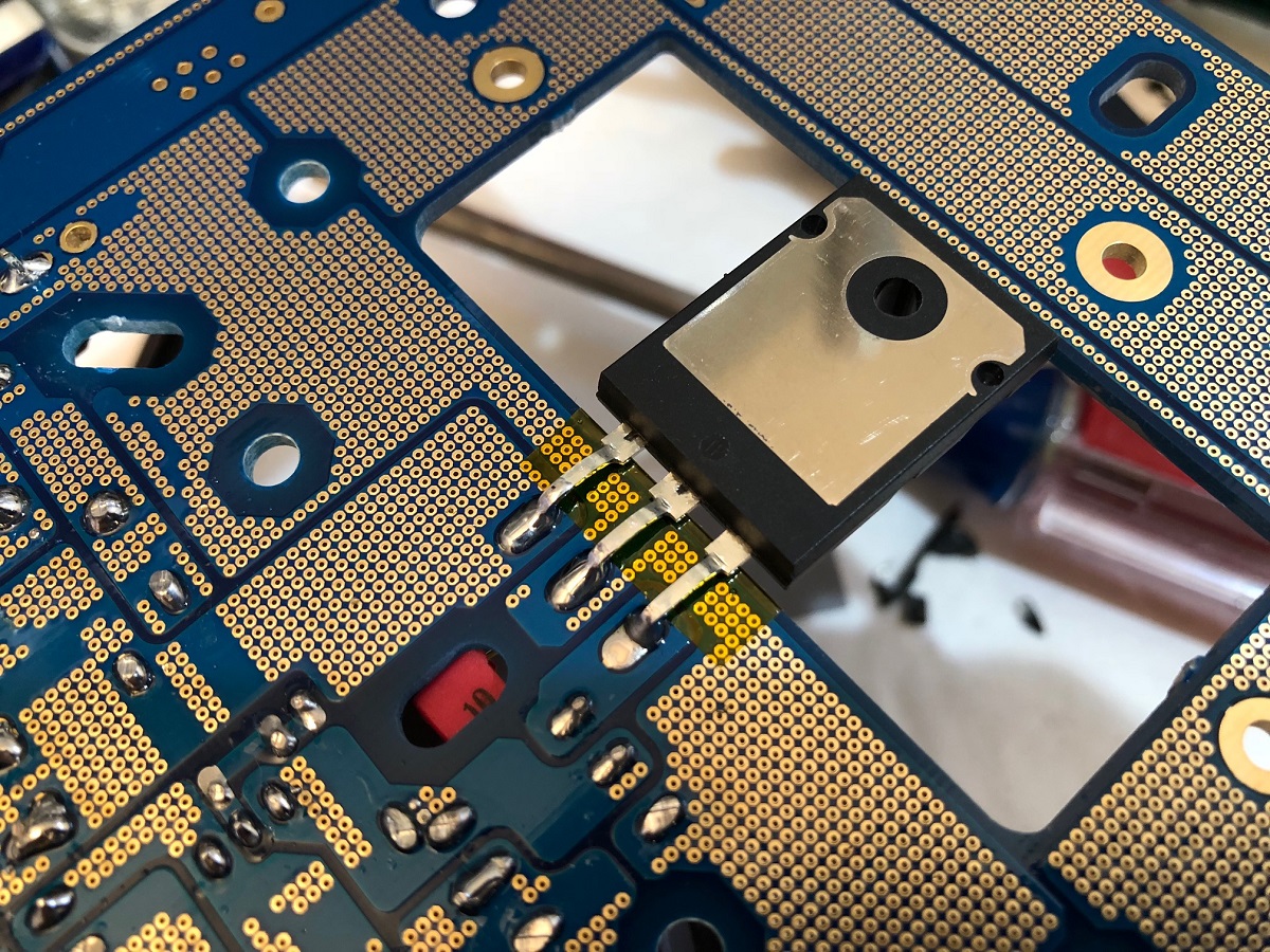
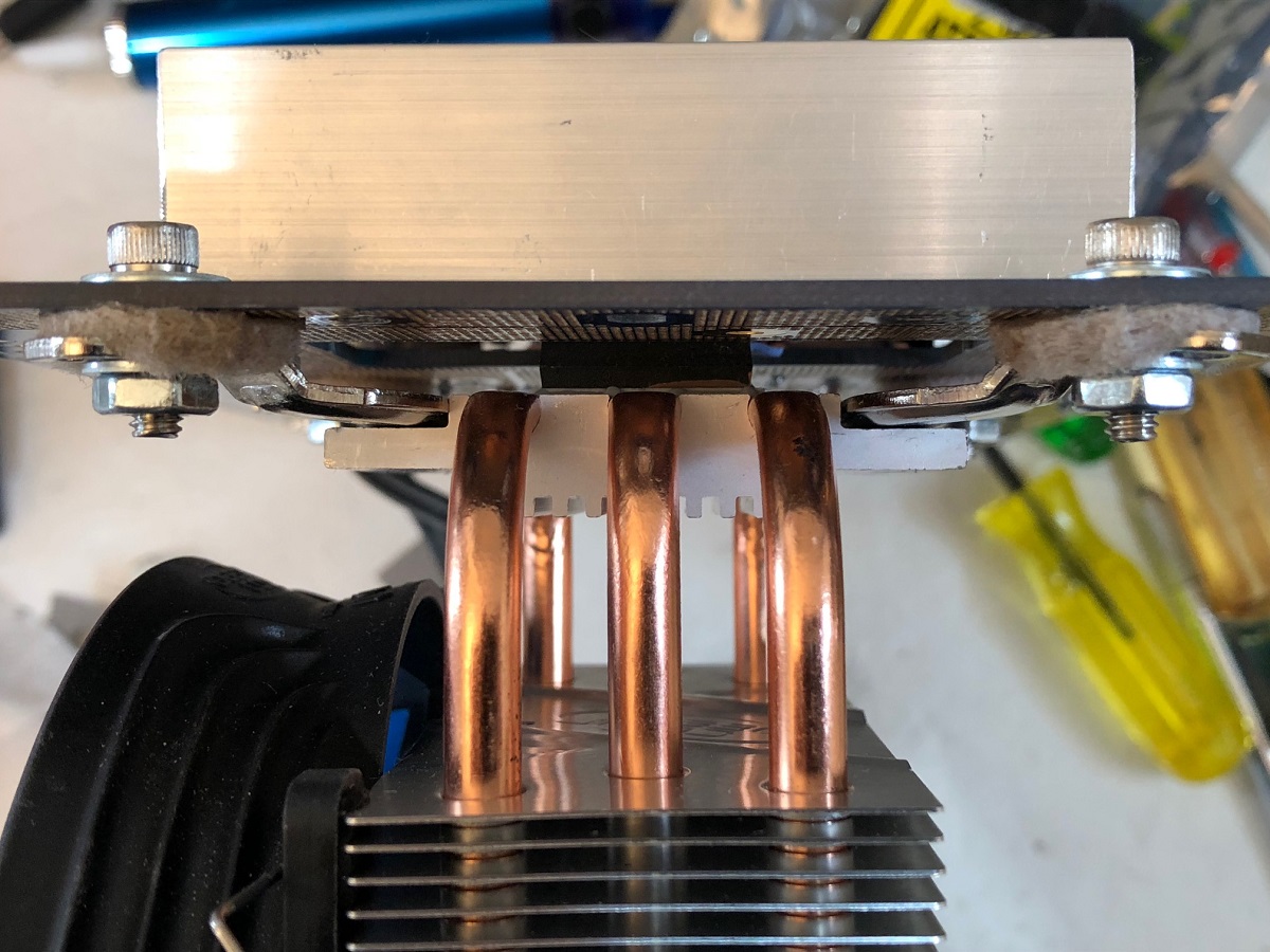
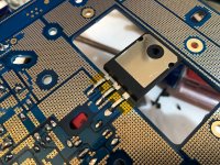
I removed the flimsy plastic snaps and opted for stainless 8-32 hex cap screws and washers with a thick felt washer to provide some compliance and vibration isolation. The top clamp is 1in aluminum L channel with two holes for M3 hec cap screws and nuts. I had one made already for the prototype Alpha 20. What are the chances that the holes drilled there exactly match the two holes JP provided for the crossbar? Well it matches perfect so I made a second one. I lined the side touching the MOSFET with Kapton tape just to eliminate any potential of the clamp touching a live part. I ended up using a 50 cent Euro coin as the spacer between the clamp bar and the MOSFET body, with a thick 1mm silicone insulator pad. On the bottom is the ceramic TO264 insulator and then I just got some heatsink paste which claims to be electrically insulating. However it looks gold (like gold metal particles in itI. Once clamped together, the Drain on MOSFET is now electrically conducting with the CPU cooler metal parts. No good - they lie. Will have to get the old fashioned white stuff from a store somewhere.
So mechanically, it all is very solid and sound - eccellent thermal contact I would imagine given the pressure it is squeezing down on the pad.
Detail of MOSFET solder joint and small Kapton tape to make sure legs don't touch:
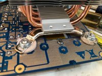
Detail of felt washers and how CPU cooler frame is mounted:
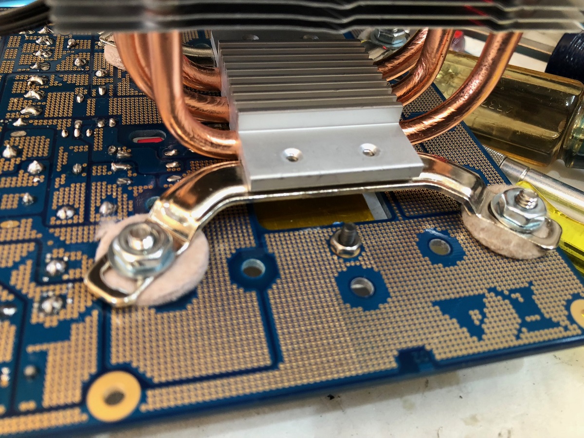
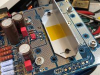
Detail of top clamp bar, Kapton lined underneath and small patch on top if for correct emmittance for IR thermometer reading:

Detail of stack-up of CPU cooler, MOSFET and board:
Everything is ready for first test except heatsink paste was incorrect. Will need to change that out.
I removed the flimsy plastic snaps and opted for stainless 8-32 hex cap screws and washers with a thick felt washer to provide some compliance and vibration isolation. The top clamp is 1in aluminum L channel with two holes for M3 hec cap screws and nuts. I had one made already for the prototype Alpha 20. What are the chances that the holes drilled there exactly match the two holes JP provided for the crossbar? Well it matches perfect so I made a second one. I lined the side touching the MOSFET with Kapton tape just to eliminate any potential of the clamp touching a live part. I ended up using a 50 cent Euro coin as the spacer between the clamp bar and the MOSFET body, with a thick 1mm silicone insulator pad. On the bottom is the ceramic TO264 insulator and then I just got some heatsink paste which claims to be electrically insulating. However it looks gold (like gold metal particles in itI. Once clamped together, the Drain on MOSFET is now electrically conducting with the CPU cooler metal parts. No good - they lie. Will have to get the old fashioned white stuff from a store somewhere.
So mechanically, it all is very solid and sound - eccellent thermal contact I would imagine given the pressure it is squeezing down on the pad.
Detail of MOSFET solder joint and small Kapton tape to make sure legs don't touch:
Detail of felt washers and how CPU cooler frame is mounted:
Detail of top clamp bar, Kapton lined underneath and small patch on top if for correct emmittance for IR thermometer reading:
Detail of stack-up of CPU cooler, MOSFET and board:
Everything is ready for first test except heatsink paste was incorrect. Will need to change that out.
Attachments

Last edited:
Good catch there Irrbeo. I will need to use some plastic insulator washers. It turns out drain and cooler body are one and the same if insulator on mosfet back conducts. Or a small piece of Kapton over where washer goes is good too.
Kokanee: Sound of fans is very quiet at slow speed. I will see if I can get recording - my SPL meter may be useful too.
Zman01: the PSU voltage is not sorted out. I need to try a known good 25vac 300VA trafo that I know it makes 35vdc rails.
Kokanee: Sound of fans is very quiet at slow speed. I will see if I can get recording - my SPL meter may be useful too.
Zman01: the PSU voltage is not sorted out. I need to try a known good 25vac 300VA trafo that I know it makes 35vdc rails.
Last edited:
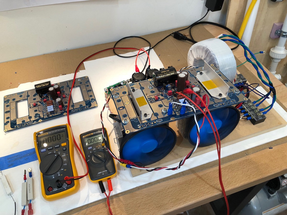
ALPHA BB First Sound
Ok, it's official, the PCBs are good and now verified to sing, and sing oh so loud.
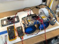
Photo of the amp with fans blowing at lowest speed and Fluke DMM shows 0.646vdc or 3.9amps:

Despite my PSU woes which limit me to a +/- 28.3v rails at 4amps bias, I am getting nice sound out of the BB. I had some trouble with a bad audio input wire for a few hours, thinking something was wrong with the amp. But just a bad cable so weak music was coming out.
As usual, the amp fired up without incident - smooth quick ramp to full bias in about half a second. Bias was unexpectedly high relative to sims. I will make it clear that no adjustments were necessary. DC offset is about 0mV to 1mV. But as predicted by Irrebeo, it was a hefty 6 amps with three 0.33R source resistors. I guess this could have been predicted give the single 0.33R was 2amps. I dropped to two 0.33R source resistors and two 0.39R Aleph sense resistors and am running at 4amps bias now (technically 3.903amps).
On my full range W5-2143 speaker in XKi cabinet, the sound is clean, smooth, and bass is with authority. I got some complaints from family upstairs that the full range speaker was playing too loud. It was clean and undistorted so I could not gauge the loudness.
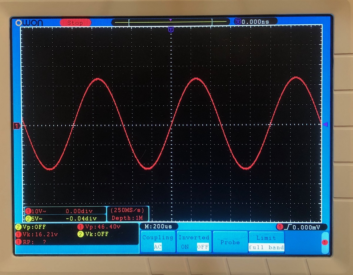
I put a 25w dummy load on the amp and hit it with 1kHz test tone and with this crippled PSU, I was able to get 46.4vpp, that's 33.6w into 8ohms of pure Class A power. I don't think I have ever heard a pure Class A amp that's capable of 34wrms before, let alone 52w once I figure out what's going on with the PSU.
Here is the O-scope screen shot of 46.4vpp:
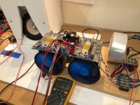
With 3.903amps bias at +/-28.3v is 221w total (110w each CPU cooler) and the CPU cooler is working its heatpipe magic. The MOSFET body temp (at the Kapton patch) on the aluminum crossbar is 41C (P-chan) and 37C (N-chan) and the heatsink fin temps are 31C and 30C. I can touch the crossbars and it is comfortable to touch. That ceramic insulator pad and heatsink compound is working well. I am using some TO220 silicone insulator pads for isolating the CPU cooler mounting boards from the exposed MOSFET drain pours.
For a 221w quiescent dissipation Class A amp, you would never guess it it that much as the temps are all very comfortable and easy to touch. I can say for sure that the upside down heatpipes work just fine. The other benefit is that the exhaust air from the CPU coolers is directed across the small heatsinks on the TO220 diodes of the PSU which can get quite hot.
Thank you JPS64, for another perfect layout, works as designed, and sounding good. I will let it burn in for a while before taking some FFT measurements. Will debug the whole high voltage drop on the PSU issue in the meantime.
All is not perfect though, I have 2.5mVrms noise (hum) in the output and trying to figure out where it is coming from. It might just be from the large ripple (67mVrms) in the PSU due to the high current draw on the amp.
Ok, it's official, the PCBs are good and now verified to sing, and sing oh so loud.
Photo of the amp with fans blowing at lowest speed and Fluke DMM shows 0.646vdc or 3.9amps:
Despite my PSU woes which limit me to a +/- 28.3v rails at 4amps bias, I am getting nice sound out of the BB. I had some trouble with a bad audio input wire for a few hours, thinking something was wrong with the amp. But just a bad cable so weak music was coming out.
As usual, the amp fired up without incident - smooth quick ramp to full bias in about half a second. Bias was unexpectedly high relative to sims. I will make it clear that no adjustments were necessary. DC offset is about 0mV to 1mV. But as predicted by Irrebeo, it was a hefty 6 amps with three 0.33R source resistors. I guess this could have been predicted give the single 0.33R was 2amps. I dropped to two 0.33R source resistors and two 0.39R Aleph sense resistors and am running at 4amps bias now (technically 3.903amps).
On my full range W5-2143 speaker in XKi cabinet, the sound is clean, smooth, and bass is with authority. I got some complaints from family upstairs that the full range speaker was playing too loud. It was clean and undistorted so I could not gauge the loudness.
I put a 25w dummy load on the amp and hit it with 1kHz test tone and with this crippled PSU, I was able to get 46.4vpp, that's 33.6w into 8ohms of pure Class A power. I don't think I have ever heard a pure Class A amp that's capable of 34wrms before, let alone 52w once I figure out what's going on with the PSU.
Here is the O-scope screen shot of 46.4vpp:
With 3.903amps bias at +/-28.3v is 221w total (110w each CPU cooler) and the CPU cooler is working its heatpipe magic. The MOSFET body temp (at the Kapton patch) on the aluminum crossbar is 41C (P-chan) and 37C (N-chan) and the heatsink fin temps are 31C and 30C. I can touch the crossbars and it is comfortable to touch. That ceramic insulator pad and heatsink compound is working well. I am using some TO220 silicone insulator pads for isolating the CPU cooler mounting boards from the exposed MOSFET drain pours.
For a 221w quiescent dissipation Class A amp, you would never guess it it that much as the temps are all very comfortable and easy to touch. I can say for sure that the upside down heatpipes work just fine. The other benefit is that the exhaust air from the CPU coolers is directed across the small heatsinks on the TO220 diodes of the PSU which can get quite hot.
Thank you JPS64, for another perfect layout, works as designed, and sounding good. I will let it burn in for a while before taking some FFT measurements. Will debug the whole high voltage drop on the PSU issue in the meantime.
All is not perfect though, I have 2.5mVrms noise (hum) in the output and trying to figure out where it is coming from. It might just be from the large ripple (67mVrms) in the PSU due to the high current draw on the amp.
Attachments

Last edited:
X,
This is excellent news!! Also, good to know that the cpu coolers can be mounted upside down which opens up more enclosure design ideas.
I was planning to use the same psu boards, hopefully you are able to work the low voltage issue out. Thanks for paving the way
Cheers,
Vunce
This is excellent news!! Also, good to know that the cpu coolers can be mounted upside down which opens up more enclosure design ideas.
I was planning to use the same psu boards, hopefully you are able to work the low voltage issue out. Thanks for paving the way
Cheers,
Vunce
- Home
- Amplifiers
- Solid State
- Aksa Lender P-MOS Hybrid Aleph (ALPHA) Amplifier