Nice ")
(For maybe a slightly different(deepcool 4heatpipes) cooler you can find the measured temp and noiselevels at 125W and other continuous loads here Deepcool AMD Heatsink Temperature Comparisons - Gammaxx S40 FrostyTech Review ) You can set speed very low when 25 degrees above ambient is the target)
(For maybe a slightly different(deepcool 4heatpipes) cooler you can find the measured temp and noiselevels at 125W and other continuous loads here Deepcool AMD Heatsink Temperature Comparisons - Gammaxx S40 FrostyTech Review ) You can set speed very low when 25 degrees above ambient is the target)
Beautiful work, X, and lovely layout of JPS with exquisite care with the cooling towers. I'm delighted with the cooling too, at 44C on the body of the mosfet it will last forty years.
I hope you can resolve the power supply. I suspect it's just too much loss on the CRCRC, and maybe the toroid is not regulating a high load. Most 300VAs will do around 6.5% or even better; but if you are pulling high loads the rectifiers don't get up to the crest in the reservoirs, so you lose more than you expect. I suspect a 28Vac might be better because under load, say 25Vac, and then you'd hopefully have your 36V rails. Correspondingly, on low quiescent with Class AB amps the toroids always deliver more voltage; 45Vac delivers more than 64V on my Maya, theoretically I'd expect around 63.5V.
We await your thinking of the sound. I predict that this 50W amp will scale to almost a 100W if it were an AB. I do not know why this happens but Class A always sounds huge.
Congratulations for making my amp design a reality!
Hugh
Alpha BB Amp Testing Update - 3amp Bias Current Fixed
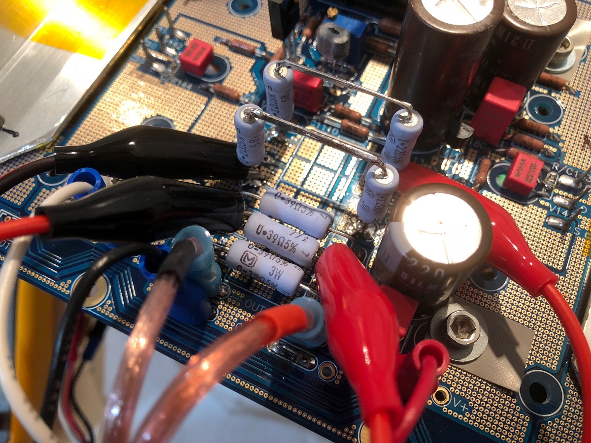
Well I was able to get the perfect resistor settings for a 3 amp bias. I used qnty 4 x 0.22R 3W Panasonic ERX in series-parallel for 0.22R and 12W. Should really reduce distortion as heat generated is almost none. Bias comes in at 2.95amps. The corresponding Aleph feedback resistors should be about 1/2 the resistance of source resistors so I left it as qnty 3 x 0.39R in parallel for 0.13R effective and 9w capable (dissipation only needed when high AC swings involved). With this change, the rails are at +/-29.0v now. At 8.0vpp 1kHz I got some reasonable values for the AC voltages across the resistors (they should be about equal for the best balance of push-pull from the Aleph CCS).
Here is the new resistor setup:
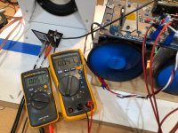
Here is photo of the two AC rms voltages with 8.0vpp 1kHz applied to check the Aleph CCS balance (the values should be similar):

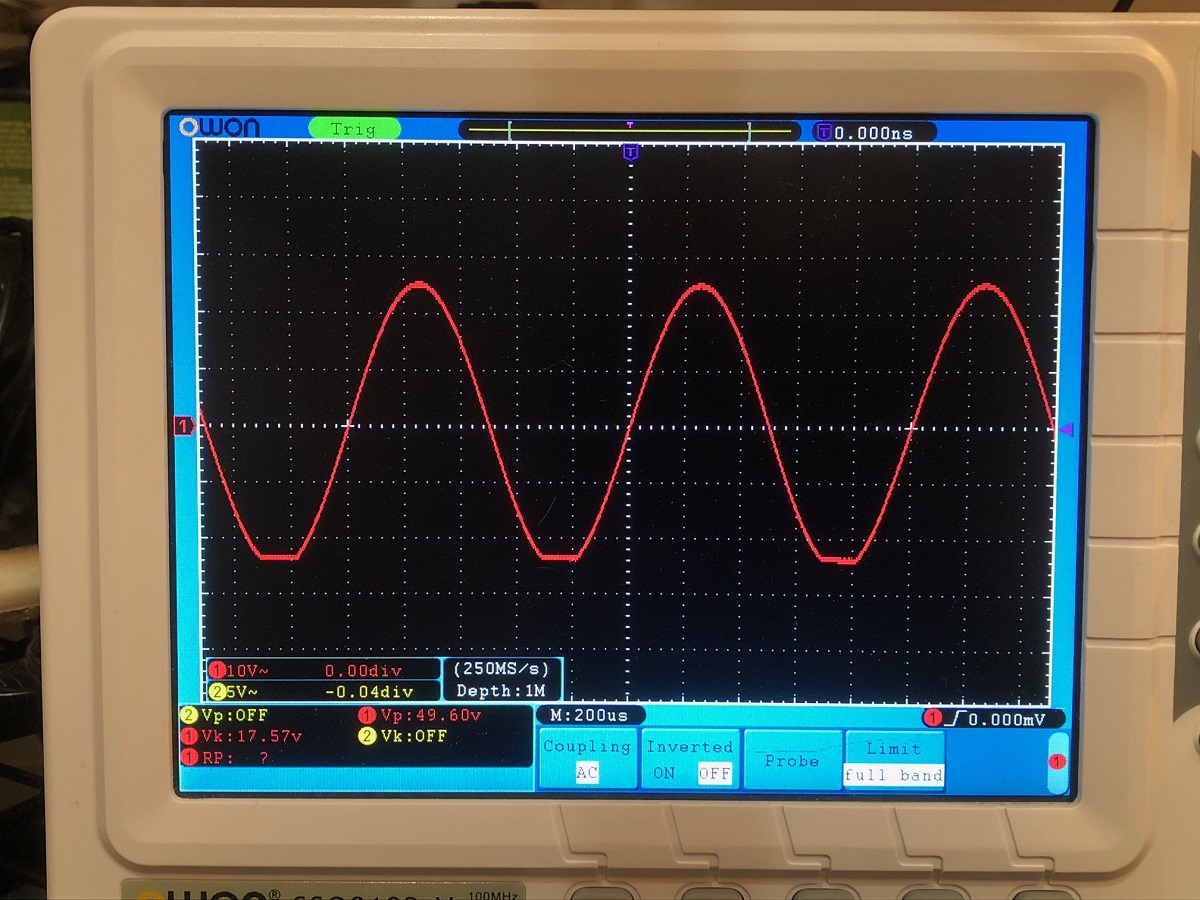
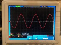
Here is a scope shot of the clipping behavior (+/-29.0v rails), it clips on the negative rail first (at clip power is 38wrms):
So listening to it now on mono test speaker and sounds very nice, can get very loud and not sound strained. I think I need to fix the PSU voltage dropout issue to try and get the full 52wrms. A 400VA 25vac trafo should put out more that +/-29vdc at 3amps. I may try a monolithic square puck bridge and couple that into the current CRC beyond the diodes.
Then try to figure out where the 2.5mVac ground loop hum is coming from. DC offset is still 0mV to 1mV at all times and all heat loads. Fans are running at 25% setting, and it is too much cooling, if I could go slower, it would be even more quiet. Temps are 37C on P body and 33C on N body and 28C for heatsink fins on both sides. Barely warm.
Well I was able to get the perfect resistor settings for a 3 amp bias. I used qnty 4 x 0.22R 3W Panasonic ERX in series-parallel for 0.22R and 12W. Should really reduce distortion as heat generated is almost none. Bias comes in at 2.95amps. The corresponding Aleph feedback resistors should be about 1/2 the resistance of source resistors so I left it as qnty 3 x 0.39R in parallel for 0.13R effective and 9w capable (dissipation only needed when high AC swings involved). With this change, the rails are at +/-29.0v now. At 8.0vpp 1kHz I got some reasonable values for the AC voltages across the resistors (they should be about equal for the best balance of push-pull from the Aleph CCS).
Here is the new resistor setup:
Here is photo of the two AC rms voltages with 8.0vpp 1kHz applied to check the Aleph CCS balance (the values should be similar):
Here is a scope shot of the clipping behavior (+/-29.0v rails), it clips on the negative rail first (at clip power is 38wrms):
So listening to it now on mono test speaker and sounds very nice, can get very loud and not sound strained. I think I need to fix the PSU voltage dropout issue to try and get the full 52wrms. A 400VA 25vac trafo should put out more that +/-29vdc at 3amps. I may try a monolithic square puck bridge and couple that into the current CRC beyond the diodes.
Then try to figure out where the 2.5mVac ground loop hum is coming from. DC offset is still 0mV to 1mV at all times and all heat loads. Fans are running at 25% setting, and it is too much cooling, if I could go slower, it would be even more quiet. Temps are 37C on P body and 33C on N body and 28C for heatsink fins on both sides. Barely warm.
Attachments
Last edited:
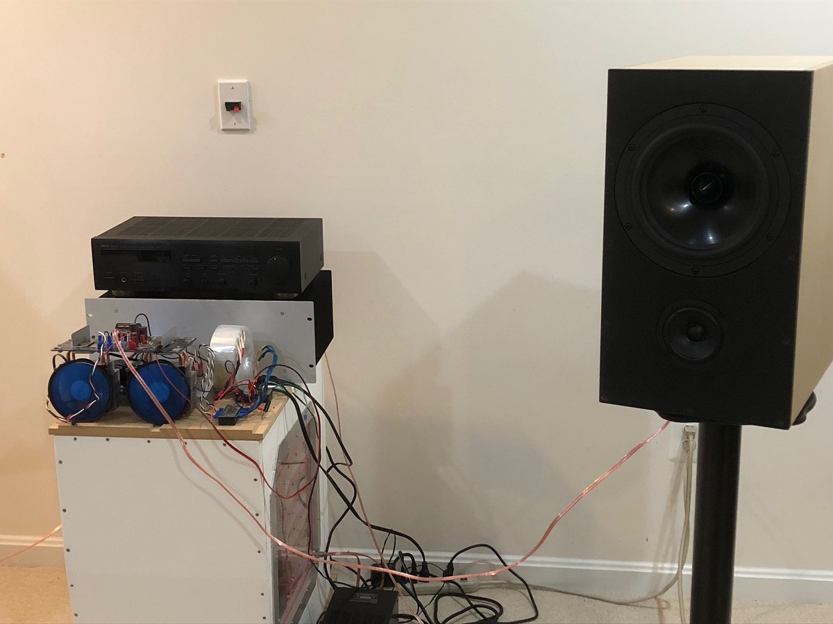
I bypassed the MUR880 diodes on the CRC with a pair of external square 35amp puck bridges and got the same thing as the on-board bridges. I changed the R on the CRC from 0.235ohm to 0.11ohm and got a few more volts, now at +/-30.0Vdc under load of 3amps. 33.5vdc with no load. Moved it over to my main 10F/RS225 FAST speakers for a listen. Listening now - plays very loud and clean. Very nice.
So I think the trafo is the issue. This is an Antek 400VA 25VAC, model AS-225. I might need to return or exchange them as I need 35v rating under load.
So I think the trafo is the issue. This is an Antek 400VA 25VAC, model AS-225. I might need to return or exchange them as I need 35v rating under load.
Attachments
Hi X,
Try the PSU Designer.
A very good tool to simulate the voltage drop and ripple of a PS.
Be sure to enter the correct resistance of the transformer,
and you'll get accurate simulation results.
I had to run it as administrator to be able to load .psu files.
Looking good your BB !
The heat dissipation system seems to work very good.
Regards,
Danny
Attachments
Last edited:
Thanks, Danny. I will look into it. I understand that load draws the current and droops the DC voltage. The strange thing is, I have always noticed that the DC voltage from after the bridge with a CRC or even C is pretty close to 1.41 x Vac. The Vac is 27v yet, Vdc is only 33.5v under no load.
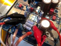
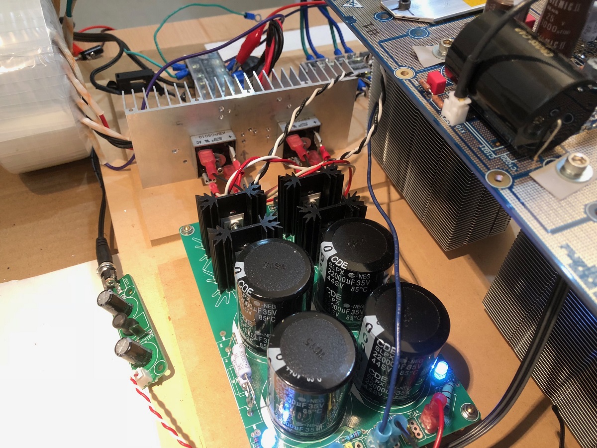
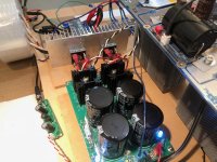
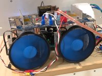
Closeup of amp showing heatpipes visible underneath:
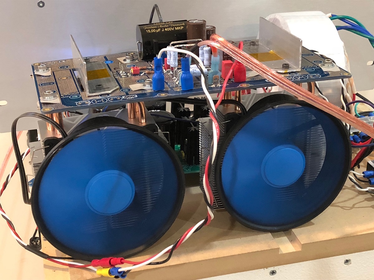
Closeup of amp showing heatpipes visible underneath:
Attachments
In an SE amp, more so than any other amp, the power supply design is the most important aspect of the system. If you have a bad power supply then you can wave the amplifier characteristic sound good-bye.
Designing the power supply starts from the amplifier side, then work backwards. If the amp needs 3 amp at +-25V, then that is what should be seen after the CapMX. You should design the capMX to drop no more than 4V and easily pass the 3 amp. Now you have the rms voltage of the transformer being 25V + 4V= +-29V rms at 3 amp which translates to 2 x 87VA. Now the mains stability is 5% so you need at least 182VA.
The transformer for a single channel will be 30.5V plus two diode drops of 1,4V = 31.8 V rns @ 3 amp or a 190VA transformer. The voltages have to be correct to operate the amp as specified. Never skimp on power supply. It is what makes an SE amp.
Nico,
Your analysis is assuming the 20w Alpha 20 amp with 25v rails. This is the 52w amp with 3amp bias and +/-35v rails, so I spec'd a 25vac trafo rated for 400VA. It is rated at 115vac and my local power is 125vac, so 1.087 factor x 25vac = 27.2vac. That's what I measure at the secondaries. But when put into a bridge, out comes 33.5vdc rather than the expected 38.3vdc. My thinking was that under load it droops maybe 3v for 35vdc. 400VA trafo should be good for 210VA right?
No cap Mx here, just a CRC.
I wonder if it is something to do with my 35v rated caps here - they are near the limit and shirting our or something?
Build a new psu with different brand caps. United Chem are $6ea for 33mF 35v. 50v are just too expensive.
EKMH350VNN333MA63T United Chemi-Con | Mouser
Last edited:
What is the voltage drop over the 0r11 ? Is it what it should be with your bias ? Or can't we use that because the capacitors after the R also form a voltage divider ? I hate this and I don't even have it myself
Same as measured by source resistors on amp. So 0.33v for 3amps. I was using this to double check my current through the amp and thus match.
What too expensive, power supply is one of the important aspects of amplifier, Jensen cap ixys linear l2 mosfets and golden pcb tracks. Use your dual tracking lab supply for proto pcb and check that its stable under load other than resistor 8R at 1Khz sinetone.Nico,
Your analysis is assuming the 20w Alpha 20 amp with 25v rails. This is the 52w amp with 3amp bias and +/-35v rails, so I spec'd a 25vac trafo rated for 400VA. It is rated at 115vac and my local power is 125vac, so 1.087 factor x 25vac = 27.2vac. That's what I measure at the secondaries. But when put into a bridge, out comes 33.5vdc rather than the expected 38.3vdc. My thinking was that under load it droops maybe 3v for 35vdc. 400VA trafo should be good for 210VA right?
No cap Mx here, just a CRC.
I wonder if it is something to do with my 35v rated caps here - they are near the limit and shirting our or something?
Build a new psu with different brand caps. United Chem are $6ea for 33mF 35v. 50v are just too expensive.
EKMH350VNN333MA63T United Chemi-Con | Mouser
The transformer antek 400va is working with 2 bridge rectifiers and the R in the CRC do you want more volt from power supply output use smaller R or variac.
When your done with proto you will know is it worth or not.Yes, I suppose 16 x 33mF 50v caps ($10ea) to fill up two of JPs64 F6 PSU’s is not that much in the scheme of things. Don’t forget the 16 x TO247 MUR ultrafast diodes at $2.50ea.
It's value can be measured in different & many other ways for the diyer
Well, I found out what the two pots on the eBay PWM fan controller do: they allow you to set the minimum fan speed manually. I turned the pot all the way CCW and the fan is almost inaudible. The SPL meter did not register 30dBA until I brought it within 6in of the blades. The other trick is to use the Fan 2 and Fan 3 connectors as those can go down to the minimum 10%. Whereas Fan 1 goes only to 20%. The fan on my laptop is much louder and more annoying.
So 6in is .154m and at 1m, that is 6.5x father away, or about -7.5dB less or 22.5dBA absolute at 1m. Pretty much within the room ambient noise - circa 30dB to 42dB for my listening room depending on time of day.
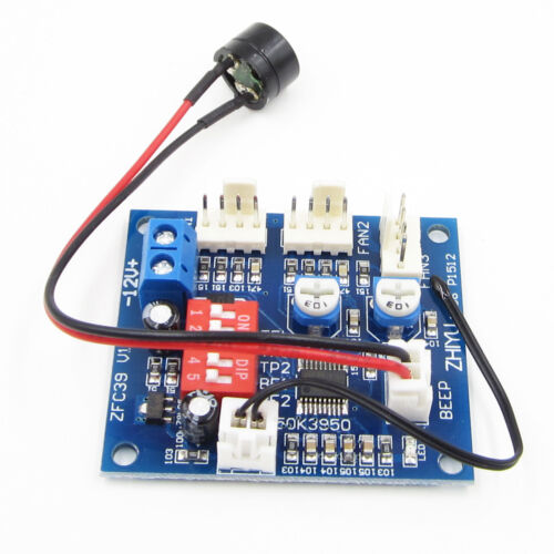
I am using the following DIP switch settings (1 to 5): OFF/OFF/ON/OFF/ON
If you want to get these, do a search for "PWM fan controller CPU" on eBay and you get dozens of hits. About $3ea.
So 6in is .154m and at 1m, that is 6.5x father away, or about -7.5dB less or 22.5dBA absolute at 1m. Pretty much within the room ambient noise - circa 30dB to 42dB for my listening room depending on time of day.
I am using the following DIP switch settings (1 to 5): OFF/OFF/ON/OFF/ON
If you want to get these, do a search for "PWM fan controller CPU" on eBay and you get dozens of hits. About $3ea.
Last edited:
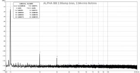
I am still working on the PSU issue, and also perhaps related to the PSU is that the amp has about 2.5mV 60Hz hum - which is audible at about 25cm away from the speaker - as I am used to having 0.2mV noise on my amps. So the PSU needs a lot more work. I will have to order qnty 16 x 33mF 50v caps in order to put this to rest.
In the meantime, I can look at the amp's performance to the right of the 1kHz excitation. Here is the first FFT for 1kHz 2.84vrms into 8ohms. A very nice profile showing low noise floor, and dominant 2nd order and lower 3rd order and THD of 0.0031%.

Source was Cayin N3 with AK3390EN DAC playing 1kHz test tone file generated from Audacity as FLAC. Signal going through Aksa Lender preamp for volume control. Vrms measured using Fluke 101.
In the meantime, I can look at the amp's performance to the right of the 1kHz excitation. Here is the first FFT for 1kHz 2.84vrms into 8ohms. A very nice profile showing low noise floor, and dominant 2nd order and lower 3rd order and THD of 0.0031%.
Source was Cayin N3 with AK3390EN DAC playing 1kHz test tone file generated from Audacity as FLAC. Signal going through Aksa Lender preamp for volume control. Vrms measured using Fluke 101.
Attachments
Last edited:
X,
With a toroid struggling to deliver the rated voltage, it tells me it's not a very good one and maybe it's distortion the waveform of the mains input. This will be producing lots of noise and artefacts, and this will pass through to the amp. I'm beginning to think a better toroid with a rating of 28Vrms output for each channel is needed, and I'd suggest a full on bridge for each rail. Only a CRCRCR will scotch this mains noise, and it should be at the rail under power no more than 50mVrms.
Nevertheless, don't imagine you are not progressing.........
Hugh
Hi Hugh,
After adding a 10mF//0.22R//10mF CRC on top of the existing CRC, the ripple under power is now 32mV. Hum is still there, so I have to look at either perhaps the toroid is too close to the amp and radiating EMI, or maybe I have an inadvertant ground loop created by mounting the CPU cooler frame and it is touching somewhere, etc.
Edit: just moved toroid around to 16in away and below amp and no change in output noise, still 2mVrms.
I discovered that the ground plane (ring) around the PCB that touches the MOSFET crossbar clamp is floating (about 0.46vrms). I grounded that with a wire from clean 0V to the plane but that did not affect the 2mVrms output noise.
One very good thing is that there is no PWM switch noise getting into the audio path at all. So fan PWM controller and motor are relatively EMI quiet.
Last edited:
Hi X,
don‘ t forget you‘ve different ground on PCB:
- analog ground for amplifier
- digital ground for PWM electronic
- châssis ground
JP
Thanks for reminding me, JP. I think the ring is the chassis ground as it is connected to the pads beneath all the stand0ff screw holes?
- Home
- Amplifiers
- Solid State
- Aksa Lender P-MOS Hybrid Aleph (ALPHA) Amplifier