for what little its worth, I had a friend who built a push-pull stereo tube amp 25 years ago with a toroid power transformer and Lundahl outputs.. I hooked that transformer up with diodes, cap and dummy load - no amp and put it near a Cary SE output transformer hooked to a speaker. Out of the speaker came a loud hum/buzz with many harmonics that could be heard 20 feet away. He built his amp - with that toroid right up against the input tube 
Or even better a CLC.Only a CRCRCR will scotch this mains noise
With only a cap of 66mF you get about 600mV of ripple
With a CRC of 33mF-0.12ohm-33mF you get about 200mV of ripple
with a CLC of 33mF-5mH-33mF you get about 10mV of ripple, that's 20 times less compared to a CRC.
But they cost more than 20 times and take 20 times more place and weight
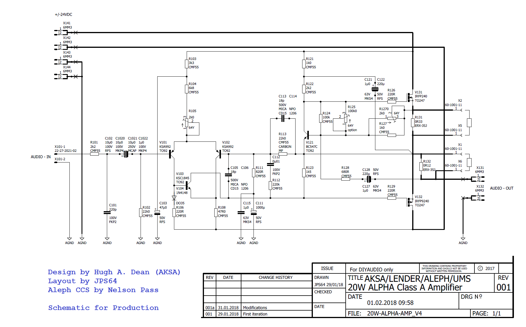
Hugh solved the hum riddle: the LTP suppy smoothing cap C014, is not supposed to be connected to the signal ground (lifted with 10R) but the power ground. I reconnected that and changed from 47uF to 1000uF 63v cap while I was at it and hum is now gone. Measures 0.5mVrms at the amp output.
Thanks, Hugh!
That is one change we caught that needs to be implemented in the production GB boards.
Thanks, Hugh!
That is one change we caught that needs to be implemented in the production GB boards.
In audio amplifier PCB that is a good question.Stupid question, but what's the idea behind the 1000s of small pads with the holes all over the PCB?
Stupid question, but what's the idea behind the 1000s of small pads with the holes all over the PCB?
The millions of vias effectively more than doubles the actual copper trace thickness because both sides are used, but since it is Swiss cheesed, it is like a porous braid for max current. It also anchors the traces almost eliminating trace peel-off.
... so I spec'd a 25vac trafo rated for 400VA. It is rated at 115vac and my local power is 125vac, so 1.087 factor x 25vac = 27.2vac. That's what I measure at the secondaries. But when put into a bridge, out comes 33.5vdc rather than the expected 38.3vdc. My thinking was that under load it droops maybe 3v for 35vdc. 400VA trafo should be good for 210VA right? ...
A transformer rated for 115Vac is designed for a maximum input voltage of 115Vac, sometimes it may have little extra headroom as tolerance, but not necessarily.
When you put 125Vac into a 115Vac rated transformer, you could saturate the core, the inductance drop through the floor and you no longer get the output voltage you expect. If you try putting 230Vac on the primary, I bet you'll get smoke instead of 50Vac output from that transformer.
Nico,
Your analysis is assuming the 20w Alpha 20 amp with 25v rails. This is the 52w amp with 3amp bias and +/-35v rails, so I spec'd a 25vac trafo rated for 400VA. It is rated at 115vac and my local power is 125vac, so 1.087 factor x 25vac = 27.2vac. That's what I measure at the secondaries. But when put into a bridge, out comes 33.5vdc rather than the expected 38.3vdc. My thinking was that under load it droops maybe 3v for 35vdc. 400VA trafo should be good for 210VA right?
No cap Mx here, just a CRC.
I wonder if it is something to do with my 35v rated caps here - they are near the limit and shirting our or something?
Build a new psu with different brand caps. United Chem are $6ea for 33mF 35v. 50v are just too expensive.
EKMH350VNN333MA63T United Chemi-Con | Mouser
I thought that it is 25v at 3 amp you need. By the way non of your calculations above are correct. You do not know if your voltmeter measures rms or average, check it on a scope, at least you will know the peak voltage. Do you know what the volt-drop across the diode bridge is, at what current. Also what is the volt-drop expected across the conductor. Have you any idea of the transformer regulation. Probably not. As I say the power supply is the most important part of amplifier design. Too many "designers" just throw together a PSU because it seems simple.
Thank you Nico!
Did you sell many of the ZEUS amps, made in Canada I understand?
Hugh
Hi Hugh,
I hoped to be invited into the company, but they went immediately to China. I basically wasted my time and effort for nearly two years from concept to final product.
What part of my calcs are wrong (they do assume the mains follows sine wave pattern). I do have a scope and can use that to look next. The design of the Project16/Prasi CRC PSU was perhaps for a much lower bias current amp (USSA5 25w F5 type amp) running 1.2amps, and even then the designer spec’d 4x33mF caps. But I am not designing a PSU here, just using one from another project to get started. The transformer is probably not putting out a sine wave. That’s the only thing that can explain why 27VAC under full wave bridge is only 33.5v under zero load. The diodes are fine I would imagine. I tried both the on board quad MUR880 and external 4-pin block.
This PSU with another trafo produced the expected 1.41x voltag
This PSU with another trafo produced the expected 1.41x voltag
Have a look see what the diodes spec is under current. Is the transformer rated 60 Hz it is very different from 50Hz. What is the transformer regulation as Hugh explains 6% is probably minimum required else it will run very hot. As earlier comment asked what input voltage the transformer is designed for, if it is 110V instead of where you are then you can expect greater magnetizing current and transformer will saturate easily. If it saturates the waveform changes and your rms calculations do not apply at all anymore.
Trace your power supply using your scope under full load, and find the point where the math makes no sense then try analyse it.
Final question is why do you run a 4 amp (or even 3 amp) bias current can you explain how you derived this bias.
Trace your power supply using your scope under full load, and find the point where the math makes no sense then try analyse it.
Final question is why do you run a 4 amp (or even 3 amp) bias current can you explain how you derived this bias.
Last edited:
......This PSU with another trafo produced the expected 1.41x voltag
Then use another transformer, unless this project is not earmarked as a keep.
If you are such an enthusiastic DIYer as I have come to notice, then I would have a multi (tapped) voltage transformer wound with at least 15 amps on tap, add the CLCLC circuits that you wish and you can select the voltage required for almost any project.
Is the transformer rated 60 Hz it is very different from 50Hz.
It is an Antek AS-4225 (400VA, 25V), designed for use in North America 60Hz mains.
Description
The 400VA toroidal audio power transformers have static shield between primary and secondary coils to improve the isolation and noise interference. They are specially designed to work on all standard 115V or 230V at 50Hz or 60Hz. These transformers have heavier gauge wires than the normal requirement to avoid the copper lost during the full power output. And they also have the magnetic shield around the outside to reduce the magnetic leakage. The dielectric test is more than 3500V in between primary and secondary coils. In most of the cases, this transformer can be output 20% more power from its rating at 60Hz power source without any problem. This transformer comes with 1 rubber pads and all mounting hardware.
if it is 110V instead of where you are then you can expect greater magnetizing current and transformer will saturate easily. If it saturates the waveform changes and your rms calculations do not apply at all anymore.
It is rated for 115v and my mains are 125v.
Final question is why do you run a 4 amp (or even 3 amp) bias current can you explain how you derived this bias.
The 3amps was the optimal bias that Hugh set based on LTSpice sims for good balance between, power into rated load, low distortion, and thermal dissipation.
If you are such an enthusiastic DIYer as I have come to notice, then I would have a multi (tapped) voltage transformer wound with at least 15 amps on tap, add the CLCLC circuits that you wish and you can select the voltage required for almost any project.
I guess I went about it the wrong way, and rather having multi-tap, I have individual ones (15v, 18v, 20v, 25v, 28v, 32v, 35v, 42v,...). These are all the ones that are currently free. The 400VA 18VAC is tied up at present driving the Alpha 20. And a bunch of other smaller 25VA 15VAC ones are on smaller headphone amps and such.
Apparently, the regulation on the AS-4225 stinks. For 3amps (full load on an 8amp rated trafo), I am getting 3.5v droop from 33.5 to 30.0v or 11.7% regulation. Much much higher than the typical 3% considered "good". I have an Avel Lindbergh 300VA 25V trafo that I should just put in and see how it does. Next will trace with O-scope and see where it becomes un-hinged.
Attachments

Last edited:
I measured my AC mains with an O-scope and it looks pretty badly distorted. It measured 320vpp and 124vrms but resembles a rounded sawtooth with clipped tops and bottom. Pretty ugly, but the other transformers don't seem to mind. I can see why some people get a power conditioner where they rectify and invert and generate their own clean sine waves.
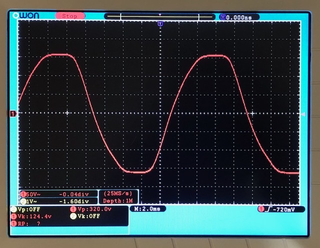
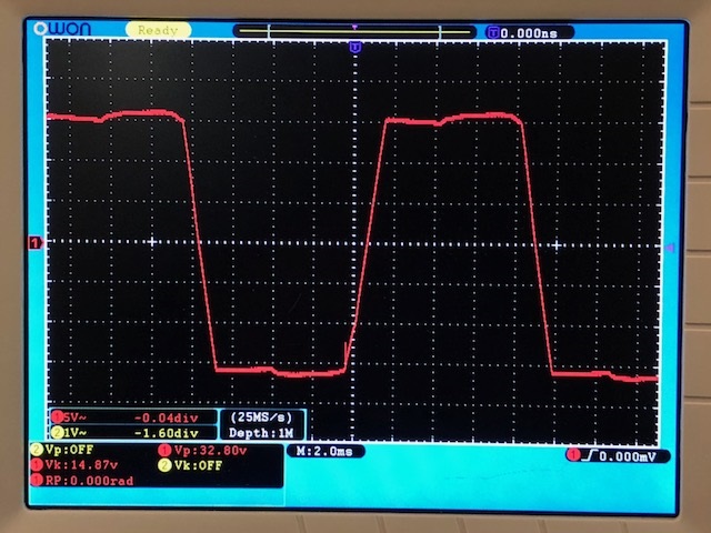
I tried several different outlets and all without any big load running in the house. Just the distortion in the mains will make some nasty higher order harmonics at the bridge. The output of the secondaries leading to the bridge looks like low slew rate square wave. This is under load with amp on and flowing 3amps, We get 32.8vpp:
Here is the waveform of the secondaries before the bridge under no load conditions (bridge still connected but amp +ve and -ve disconnected). We get 35.2vpp:
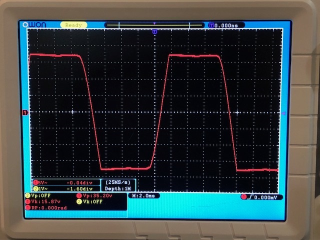
So this may explain in part the strange behavior I am getting. With the secondaries flat topped like that, does that mean the transformer is saturated or is it supposed to look like that leading to a rectifier bridge?
What does your AC mains look like on a scope?
I tried several different outlets and all without any big load running in the house. Just the distortion in the mains will make some nasty higher order harmonics at the bridge. The output of the secondaries leading to the bridge looks like low slew rate square wave. This is under load with amp on and flowing 3amps, We get 32.8vpp:
Here is the waveform of the secondaries before the bridge under no load conditions (bridge still connected but amp +ve and -ve disconnected). We get 35.2vpp:
So this may explain in part the strange behavior I am getting. With the secondaries flat topped like that, does that mean the transformer is saturated or is it supposed to look like that leading to a rectifier bridge?
What does your AC mains look like on a scope?
Attachments


Last edited:
In fixing the hum issue by changing the negative lead from C114 from the signal ground (10R lift) to power ground (0v), I took opportunity to put in a big 1000uF cap for the LTP supply smoothing cap. It has a 3sec time constant and what this does is eliminate startup thump on the speaker. You can see the cone move in slow motion over 3 seconds. Probably a good hanger to the Alpha 20 as well to eliminate thump.
Alpha 20 schematic (it is C103) change to 1000uF:
Alpha 20 schematic (it is C103) change to 1000uF:
- Home
- Amplifiers
- Solid State
- Aksa Lender P-MOS Hybrid Aleph (ALPHA) Amplifier