Smoking-amp,Originally posted by smoking-amp Only problem is that the 3/2 power distortion is related to load current and the screen current distortion is related to load (or plate actually) voltage. All is fine with a nominal load resistor. But when you put a reactive load like a real speaker on it, the two go out of phase. This gives nasty distortion with speakers, but passes the THD meter test with flying colors.
This is a very interesting point. I am still thinking of the influence of the (ideally tight) coupling between screen and anode, as compared to the same behaviour voltage-wise, but with no coupling (sounds a little confusing, I admit).
The first part of your post is generally covered by in-situ measurements. However the action of screen and anode, the distortion measured is on the load, thus the value is the resultant of all effects. It is also a generally flat curve (again grammatically misleading!
") ), reassuring against small changes in load. But the above quoted part of your previous post must be considered. My measurement facilities are also not progressing (have just been away on another "vacation"); I would dearly like to look at this myself.
), reassuring against small changes in load. But the above quoted part of your previous post must be considered. My measurement facilities are also not progressing (have just been away on another "vacation"); I would dearly like to look at this myself.Somewhat of an aside: I have mentioned elsewhere that one must be careful of the interpretation of distortion data showing % distortion. That is of the (and at the) maximum output. If say the UL distortion figure is similar to triode but the output is double, the real distortion amplitude is also double - one does not only hear distortion compared to output at any moment; it is also audible or otherwise depending on its own amplitude. And "half output" (as for triodes) is only 3dB; not a dramatic difference, so. (I am known for my preference of UL, but also hope to stay open-minded as a hopefully good scientist!)
Postscript: Also my sincere sympathy regarding your circumstances - I have also been loosing dear friends to cancer recently.
I thought I would resurrect this thread to share me experiments with this adjustable load topology. I really, like this topology it is very foolproof in operation ther is no Bias to adjust is extremely stable as well as tolerant of a wide variations of load mismatch without any stability issues. The impedance tap switch appears to simply determine the damping and output power, Unlike most tube, Amps where there is also a noticeable change in frequency response with load impedance on any given transformer tap. It also controls the cone of the Woofer in a vented box a lot better than other SE Class A Amps I tried. It is presently used in a second system with Loudspeakers that are not friendly to a solid state Amp let alone a SE Tube unit, yet this amp dose NOT Audibly follow the wild impedance curve the speakers present.
Another nice feature is the bias of the output tubes can be adjusted slightly as needed by a trim pot on the screen grid, however the circuit as shown accommodates such a wide verity of output valves I felt adjusting the Bias was not required.
This topology is as close as I have come or experienced in a Load tolerance from valve Amplifiers. I am presently working on a push pull version using KT88’s and three stages of amplification..
Attachments
yet this amp dose NOT Audibly follow the wild impedance curve the speakers present.
I have found that the cathode feedback is the major contributor to this effect since the feedback varies with the speaker impedance. Your circuit does not apply any AC feedback to the screen, but 13K of resistance in series with the screen must have some DC stabilizing effect.
This thread was started by a few experimentors that seemed to come up with the "variable UL" idea independently at about the same time. Several experiments occurred and then the thread died. Personal circumstances prevented me from doing much tube experimenting for nearly two years, but that is changing.
I have built two different push pull driver boards and I have been hooking all sorts of things up to them. Some things (like the usual pair of KT88's) work well (as expected), some things blow up (expected as well) but every once in a while I get a stupid idea that just might work.
I built a multiple output PowerDrive board with each driver capable of independent DC voltage and AC gain and Phase controls. Wire one output to each grid (and even the cathode) of a power tube and you can turn knobs all day long. The present implementation used a P-P driver board to feed a SE amp. Further experiments are forthcomming.
I also have been trying different tube topologies from Triode to cascoded dual triodes to cascoded triode strapped 6L6’s. While playing around with these power tubes I remembered from the old ham days of directing the electron beam by strategic G2 voltages’. While researching this I found this article on OPTIMIZED ULTRA-LINEAR OPERATION http://www.webace.com.au/~electron/tubes/ulo.html
Prior to the addition of D3 as advocated also on above site, there was AC feedback from the Plate to the screen grid. Notice that this stage without D3 is similar to the Driver stage that is a cascoded operated in Ultra linear mode. The method I believe has all the advantages of using a transformer tap as in conventional Ultra linear operation, however without the stability issues. The disadvantage of this mode is not taking advantage of an opportunity to add yet another feedback loop around the output transformer further lowering distortion.
Now probably would be a good time (Since I am Going Push Pull) to think about adding a dedicated UL winding that is not connected to the primary winding at all to supply a lower screen voltage while also affording feedback around the transformer.
You are correct that adding cathode feedback totally corrected the coloration with wild Loudspeaker loads, although this was already getting quite good prior to the addition of cathode feedback. I did each mod in steppes and seriously evaluated the results prior to proceeding on to the next mod.
I like the way this is going sonically as well as measurably and it is my intent to come as close to the tonal neutrality of quality solid state with the smooth unfaltering Class A valve Sound. I do not want to disturb the present tonal balance when moving to push pull so I plan to take this circuit and bridge them together via the center tapped output transformer. Ground one input, I ill posts a rough overview of this idea when that design is finished and tested.
Old Hat; DePalma did this on an EL34 p-p amp. But doesn't quote any performance figures.Originally posted by ppl Now probably would be a good time (Since I am Going Push Pull) to think about adding a dedicated UL winding that is not connected to the primary winding at all to supply a lower screen voltage while also affording feedback around the transformer.
richy
I used that A441 OPT, and was less-than-impressed with it. I have had much better performance with the Chicago BO-xx series with cathode FB coils. The top line BO-14 is waiting in the wings for use with some big sweep tubes.Originally posted by richwalters Old Hat; DePalma did this on an EL34 p-p amp. But doesn't quote any performance figures.
The Chicago publication on use of the BO-14 OPT describes the benefits of CFB on distortion performance, and I am looking forward to playing with it.
cheers,
Douglas
Okay; the set-up looks simple:- Those with electrostatic speakers should get closer to the sound truth: However, good quality crossover networks aren't ideal as the components are tailored to represent a true impedance load from A to Z frequencies.Originally posted by smoking-amp Only problem is that the 3/2 power distortion is related to load current and the screen current distortion is related to load (or plate actually) voltage. All is fine with a nominal load resistor. But when you put a reactive load like a real speaker on it, the two go out of phase. This gives nasty distortion with speakers, but passes the THD meter test with flying colors.
>A close electrostatic LS sim is a series 20uH inductor connected to a shunted 2uF and 15Ohm resistor. Not all tube amps like electrostatic loudspeaker loads; the Quad series was designed for such task. My older Citation amp with a 15 ohm tap was often used but was near unstable with awkward loads. The Loudspeaker box simultation programs often throw crossover values and phase values together.
A way out of the analytical problem is to simulate the reactive speaker components at various spot frequencies, that is calculate the phase angle differences and present them into passive components. Place these as the load and measure at a ref level. This should aggravate non linearity distortion effects in the o/p stage.
For some reason many listeners have remarked my simple 6dB/oct crossover speaker system produces sound like no other (brilliant). Perhaps there is a deeper correlation between phase and the UL stage.
I will do such tests.
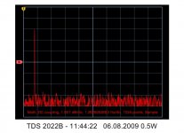
A others predicted, a straight 1Khz from a 20dB gl nfb UL 40% 7W ECL82 p-p amp into a resistive 4 ohm load at 0.5W produces sterile results. THD = near nothing. math graph pic.
richy
Attachments
OK, I don't got time right now at work to dig through 7 pages see if its allready been suggested. But G2 screen MOSFET might should be a P-Channel and operate to shunt away a constant current. This should make G2 runaway just about impossible?
And the cathode would always see screen current in parallel with mosfet shunt as a constant. If that helps in some small way to hide the event where G2 current begins to be drawn?
The CCS pullup for G2 can completely bypass the OPT or not. Whichever connection is convenient. I'm thinking bootstrap CCS may have less switching noise around the quiescent state than a two diode solution I saw near the start of this thread?
And the same shunt drive trick might extend to hide forward G1 currents in AB2 over-mega-next-to-impossiblity-drive schemeos??? Shunting protection for emissive G1 runaways too.
Well... Seemed a good idea when I wrote earlier, but since have doubts this shunt drive idea is gonna work as advertised....
Where to return shunted G1 currents??? If to the cathode, I can't pull negative. If to ground, no cancellation effect at the resistor...
For G2, bootstrapping for CCS depends where you fake UL tap??? Can't just pump the full anode swing. Both ends of the CCS resistor need to see similar swings, or the impedance might not seem high. Connection to B+ is far from ideal...
These are all fixable issues, but I didn't intend to add complexity. Always happens when I try to make a thing simpler...
Attachments
Been a while since I thought about this thread.
To build a test rig now, I would use an N channel Mosfet source follower to control the g2, with a gyrator pull-up on the Mosfet's drain from B+. Set the gyrator DC volt op point X amount of volts above the plate DC op point (and gyrator DC current then settles at the screen idle current).
Then a big capacitor from the drain can either be grounded to dump screen current or it can be connected to a UL xfmr tap, or it can connect to the plate to restore screen current to the plate output. Plate voltage can dip X volts below the screen and the Mosfet still works. Screen and gate stopper resistors and some ferrite beads on the Mosfet gate probably needed for stability.
I'm still working on an automated test rig. Have all the hardware, will soon start on the Vis Basic.
Don
I've been doing a bit of research as I'm designing a PPP Amp to use some Plitron VDV2100 CFB/H Trannies I have on the shelf. These are 30% UL + 10% Cathode Feedback, 2100 Ohms Raa. Probably a quad of KT88 will do. Using both UL and Cathode feedback would deliver voltage feedback to the screens the same as 40% UL operation (it sits on top of the cathode feedback).
In reading through the above I think that we are still missing something fundamental in the analysis.
Langford Smith and Chesterman articles on Ultralinear from 1950's clearly stated that Ultralinear was superior to both Triode and Pentode Mode with respect to Total Harmonic Distortion and Intermodulation Distortion and that the distortion levels were lower than could be accounted for by feedback theory alone. The articles also state that the screen delivers power into the output transformer and is not just a feedback mechanism (there seems to be a hint there). Using a MOSFET buffered screen drive will prevent that.
For you possible edification the articles can be found here: http://greygum.net/radiotronics/
There are also some valuable comments regarding tapping points and load impedances. Inferences I have drawn from these articles is that the 43% tapping point was optimal for EL34 (Mullard Designs) but may not be as suitable for other tubes - in particular a much lower tapping point is recommended for 6V6. In addition, I drew the conclusion that that were saying that in general Raa should be higher than used for Pentode Mode at the same operating point.
Keep up the discussion / "brainstorming"
Cheers,
Ian
One "brainstorm" - the classic UL designs often used 6146. While they are not readily available there a lot of NOS 6DQ6B around which were virtually the same tube. Maybe I should try them.
hey-Hey!!!,
The g2 tap location is selected pentode load style; we still wish to drive the load line through g1=0V to the right of the knee. Knowing where this knee lives is the problem. The knee depends on the starting point, and tap percentage. For the most part the 'triode-ization' of the curves makes guessing at this much simpler, and less critical. Still, a good combination of OP, tap location and load can deliver some very nice performance IME.
cheers,
Douglas
Originally posted by gingertube Langford Smith and Chesterman articles on Ultralinear from 1950's clearly stated that Ultralinear was superior to both Triode and Pentode Mode with respect to Total Harmonic Distortion and Intermodulation Distortion and that the distortion levels were lower than could be accounted for by feedback theory alone. The articles also state that the screen delivers power into the output transformer and is not just a feedback mechanism (there seems to be a hint there). Using a MOSFET buffered screen drive will prevent that.
For you possible edification the articles can be found here: http://greygum.net/radiotronics/
There are also some valuable comments regarding tapping points and load impedances. Inferences I have drawn from these articles is that the 43% tapping point was optimal for EL34 (Mullard Designs) but may not be as suitable for other tubes - in particular a much lower tapping point is recommended for 6V6. In addition, I drew the conclusion that that were saying that in general Raa should be higher than used for Pentode Mode at the same operating point.
Keep up the discussion / "brainstorming"
Cheers,
Ian
You rightly mention the EL34 case, a good one:- the Mullard 20W design shows 1K res in series with the screens. With this high value the effective screen power contribution in the tranny isn't much, just the little 43% tap feedback linearises the electron magics within the tube. (my coined term, transformer bootstrapped negative feedback).
We have a problem and that is the o/p tranny quality varies so much that is I find this influences UL linearity; doing the same screen tricks with 6550's with also 43% taps I find the optimum value for the circuit using an excellent quality 18 sectioned o/p tranny by Majestic similarily around 1K, but a Sowter variant again with 43% taps which uses 14 sections shows best linearity distortion values with screen values around 270R. Big differences. These trannies aren't cheap, and other vendors will probably show/give differing results. Murphies Law.
The AC phase/frequency relationship between the taps to the anode looks too influencial and with all conventional UL trannies where the UL tap is part of the anode winding, this has a very high leakage inductance. I will re-read Radiotron 4th edit again especially the circular load lines and the McIntosh approach.
The irony is that the 6550 is a true kinkless beam tetrode and the EL34 a true pentode but running the 6550 screens with 1K values confuses the picture.
I have never known a KT88 to operate with high value screen res, esp when the 6550 and KT88 are considered swaps ? NOT as I see it for akin performances.
Again there is another problem; global nfb reduces the effective amp output resistance to a few milliohms; this damping masks crossover irregularities, Or does it ? The picture couldn't be far from simple.
I've got some H.V test ideas, but need to get the Lissajous working on my scope.
richy
Instability is what made me think voltage divider. Since in my circuit with a Hammond 1629SEA Instability resulted with the Ultra-linear transformer tap I sought to use another method. Both the conventional tetrode as well as the Triode strapped mode were stable Leading me to believe that Excessive Phase shift from the transformer were the reason so I used a voltage divider and stability not only returned it became rock solid into any Load from 3 ohms to 300 Ohms using the 4 Ohm tap as the Output.
It appears that the New Dynaclone output transformer no longer has separate windings for UL and or cathode feedback like the Original Dynaco A441 has. http://www.triodeel.com/pdf/a431sdiag.pdf
It appears that the New Dynaclone output transformer no longer has separate windings for UL and or cathode feedback like the Original Dynaco A441 has. http://www.triodeel.com/pdf/a431sdiag.pdf
It appears that the A441 is not available from triode electronics. However from their Original Dynaco transformer page I quote from the A441 data “All units have taps on the primary except A-441 which has Tightly coupled Tertiary Winding” Are alternate transformers available with this winding as well as dedicated Tertiary Winding for Ultra linear operation in addition to one for cathode Bias?
Chicago Super Range( the BO-xx series ) had models with this configuration. As far as I know, the only one with separate coils for cathode, screen and anode would be Jadis. The McIntosh MA230 OPT was built with a CFB coil as well. Currently Plitron has some with CFB coil.
cheers,
Douglas
cheers,
Douglas
@ Ppl,
In your post #164 you mention the 'Optimised UL' article by Grimwood. Nobody like being negative, so let me rather take the unenviable job of advising that that particular article should be taken with a fair quantity of salt (as we say here). Interesting, but the gentleman makes several serious mistakes along the line.
Totally unprofessional to say that without proof - but to do so would take a fair quantity of space up on this here thread. Just a few markers: The theory of physical electrode spacing relating to G2 tap percentage does not hold water; some of his measurements (statements; since he is rather sparce with actual figures) of electrode spacing is quite off. I have the funny habit of cutting open tubes and mounting them for display purposes, and was able to measure tiny dimensions with fair accuracy. One cannot simply relate space charge effect to cathode-anode distance; there are other factors.
About the most informative of his figures is the KT88 typical behaviour - the 2nd figure in his epistle. You can take that as a simple illustration of general behaviour. This shows that in simple terms, UL gives us the best of the pentode and triode worlds. It's distortion is not better than triodes as is alleged, it is slightly worse; but it is close to triode performance while the maximum output and efficiency is similar to pentode operation. Neither do triodes have excessive 2nd harmonic distortion as alleged; he compares apples to pears - the triodes are in overload at the point he selects while the pentodes are not ....
.... and so forth. Not to discourage your studies into UL, but to avoid that you get bogged down in contradictions, which situation you will encounter at an early stage!
(I am not going to comment on his long argument re UL as the correct term - simply to say that nothing is ultra-linear regarding UL. It gives, for all its simplicity, a more ideal output stage than either triode or pentode/beam tubes; no more, no less.)
- Status
- This old topic is closed. If you want to reopen this topic, contact a moderator using the "Report Post" button.
- Home
- Amplifiers
- Tubes / Valves
- Adjustable distributed load discussion