Gimp,
No I haven't done any "Targetted" testing, however, there was one thing I have noted recently which gives another indication of possible UL problems.
My Baby Huey design is an EL84 Ultralinear + balanced shunt feedback from the push pull anodes design with zero global feedback.
I tried a modification to take the balanced shunt feedback from the screen taps instead of the output tube anodes (an "E-Linear" style approach if you like) being VERY carefull to keep the same level of shunt feedback. Top end accuracy and detail was adversely affected, pointing to higher frequency phase shift problems at the screen taps due to Leakage Inductance and Winding Capacitance. This MUST also affect the UL Operation. This was mod I put in the "FAILED" basket. This was using "common garden variety" Hammond 1608 Output Trannies.
Just one more observation to add to the discussion.
Cheers,
Ian
Last edited:
Did anyone finish the experiments?
My experiments have been pushed to a back burner for a while. I have limited time and have been chasing a "bigger picture" which will include distributed feedback of sorts.
I have several ideas, some my own, some proposed by others, that have been discussed on several threads scattered through this forum. The distributed load, G1=G2, E-linear, screen drive, Schade feedback, cross coupled Schade threads are a few. I decided to build a Grand Unified Theory breadboard to further the experiments. It did not go well.
The GUT breadboard had PowerDrive style mosfet drivers for G1 and G2, and a P-channel source follower to feed the cathode. Each mosfet gate could receive drive from either phase of the P-P driver or feedback from the plates of the output tubes in varying amounts. The DC output from the mosfets was adjustable over a wide range. Schade feedback could be applied to the driver plates or screens using mosfet buffers.
The results showed some promise, but I was plagued with persistent oscillation problems. The sand based life forms like to emit bursts of RF as they go into or come out of cutoff. Not a problem in class A systems, but I am trying to approach class B in high powered P-P. The board was quite good at wiping out TV reception.
I got so annoyed with this a few months back that I just twisted the power supply knob up to 650 volts and watched the board FRY!!!!! A new one is under construction. Lately there has been no time, or I haven't been home.
The original approach of using FFTs to analyze the effects of UL% changes is I think hopelessly difficult to interpret due to inadvertant bias changes/ operating point changes occuring simultaneously. Too many variables.
A big improvement would be a measurement setup that would just display gain variation versus the parameter varied. A rather useful instrument to build actually. It would apply a small constant 1 KHz AC signal to the input (while a slower DC ramp signal, summed with it, varies the input signal across the useful input range). A frequency selective converter (of the 1 KHz amplitude back to DC) from any test point, would show the gain vertically on a scope, versus the ramp signal applied to the horizontal. A constant gain thru the useful input range would display as a flat line. Any variation in gain would bend the line. Cranking up the AC scope gain on the vertical channel would enable even tiny amounts of distortion to be seen. This is considerably easier to build than a curve tracer, and far more useful. Amazing there is nothing like this around. The %UL or Load Z would then be manually varied to see the effects on the scope line straightness.
Another approach for UL testing also comes to mind:
One could use a HV Mosfet amplifier stage tacked onto an Op Amp. to drive the tube's screen grid. Configure the op amp inputs to compare the input grid signal with a scaled down (via adjustable pot.) plate output signal (since that is inverted, just sum the two at the Op Amp - input, plus a pot derived DC offset for the DC screen voltage). The Op Amp/ HV Mosfet stage drives the screen grid to try to make the (inverted) scaled plate output equal to the grid input (this will need some frequency compensation of the Op. Amp to prevent oscillation).
Then just display the screen grid voltage along with the input, or output, signal on a dual trace scope to see if it is some % of the output, or if it even looks like the output. The load Z could be manually changed to find an optimum. Anyway, this shows what the screen really wants on it for linear gain. (I would expect the apparent optimum UL% to change as the pot used to scale the output signal is varied, since varying the %UL changes the effective tube Mu, see below. But some particular scale setting will give the flattest gain curve)
(Note: The HV Mosfet stage does not even need to be particularly linear for this setup, since the Op Amp feedback will correct for that too. We just want to see what end's up on the screen grid for linear tube gain.)
Varying the %UL can be shown to be just varying the Mu of the effective triode formed by simple analysis: Mu= gm1/(U%*gm2 + gm3) The lower the Mu effective, the lower the distortion due to internal feedback. (100% UL giving triode configured Mu) But this does not take into account the screen current effects. (both subtracting from the plate signal and adding back in at the UL tap). The net effect though is to subtract some plate current out since the UL tap recombination lowers its effectiveness. So it seems likely that the increase of screen current near the plate curve knee is acting to reduce gain, versus the 3/2 power law increase of gain at the higher current. So one distortion mechanism is played off against the other. Hence the observation that UL results are better than NFdbk theory predicts.
My original complaint about UL was that this mechanism does not track for reactive loads. The screen current effect is related to plate voltage, while the 3/2 power effect is related to plate current. If the load is reactive these effects go out of phase. But for a purely resistive load they act together. Hence this UL effect looks good on a distortion analyzer with a resistor load.
Last edited:
Using a separate UL winding on the OT (to use a lower screen voltage) would eliminate most of the screen current effect, and so removes the problem of reactive loads, but would also remove that extra piece of (ie, more than NFdbk theory shows) linearizing effect (at least for resistive loads). Also makes leakage L a bigger problem too.
The other issue I see (and many others have seen too) with UL, is that it lets the tube down (lower screen V) when the load needs peak current the most.
It is more effective to take some local feedback to a driver stage where there is more loop gain available, and it does not diminish the output stage's current capability. This is why Schade like local feedbacks work so well. UL is just a cheesy screen supply. Purely cost savings.
Last edited:
Hi Gingertube, have you built this amp? How does it sounds and hot the UL tap is?Am I right in thinking that if I use the 10% cathode feedback windings in the cathodes of the output tubes and the 33% Ultralinear screen taps then I will effectively get 43% Ultralinear anyway (cause the screen to cathode volts will be 10% + 33% being opposite phase)?
Thanks
I have not folowed this for a while, thus please pardon any repetiton.
The remark by Gingertube quoted in the previous post (cannot find the original):
Yes, that would be quite correct, though some folks seem to miss this.
Then Schade or similar local feedback (Smoking-amp post #185):
One needs to keep in mind that 'outside' feedback like Schade or other similar, diminishes the stage distortion pro rata - inherent pentode characteristics remain. But the UL configuration is not just a pentode-with-feedback. It changes the operation/characteristics of the tube itself so to speak, to something between pentode and triode, with retention of the good points of both.
On a practical point (may also have stated before): I have built a 4 x 6L6GC (p.p/parallel) 100W amplifier using cathode feedback with a equivalent 33% UL tap configuration. "Burnt' my fingers somewhat, the 380Vpp signal drive required placed heavy demands on the twin triode driver stage (E182CC). Coming down to an equivalent 25% 'Tap" eased matters.
Somewhat OT: I read about exorbitant OPT designs with up to 18 sections and such. Not comparing myself with the likes of Lundahl, but I found the normal 3 secondary section arrangment optimal before internal capacities start dominating. (That is 7 sections in total - C-core iron.) Repeat: Not to wave the flag for my efforts, but for those interested in own design OPTs: Go for it! If you follow the basic OPT design procedure set out i.a. in RDH 4, you should get a good product good for 2 octaves either side of the audio spectrum, very manageable with global NFB of some 20 dB, etc.)
Thank you for your answer Johan,
my project is exactly a quad of 6L6GC in push pull per channel. What is the impedance you have used in this UL configuration?
380Vpp is quite an issue, even for the 12AU7 PI with CSS that I would like to use. What would be the required drive with a tap at 25 (+10) % tap?
Do you use bi/tri/tetrafilar in your transformers?
Thanks in advance for your reply.
Zintolo,
Going back to my notes, I used a 3K a-a load (p.p. class AB1). The circuit is UL but with the cathode feedback topology, thus enabling lower screen than anode voltage. (The 3K is the full primary impedance, anode plus cathode windings.)
Voltages: H.t. (anode) supply: +560V
Screen voltage: +460V stabilised.
Fixed bias: About -43V adjustable to give 45mA anode current per tube (standing).
Cathode windings are 28% of half primaries.
Output power at clipping: 110W with maintained anode supply voltage. (C-core OPT.)
As said the driver anode swing can be a problem; one needs to use a high gm low anode saturation voltage tube. The E182CC anodes can go as low as 30V though that is already in the saturation region. Although the E182CC operation is class A, I use fixed bias of -11V (zener-diode in the combined cathode circuit). Anode load resistors are 33K each, feeding servo-controlled 390K 6L6 grid resistors to keep from loading the E182CC anodes with the required 50K max. 6L6 grid resistors. (This needs a bit of a design to keep matters d.c. stable.)
Hope this helps.
I use an OPT as described, no bifilar windings, design as per Crowhurst in RDH IV.
Thank you again Johan,
can I ask you some more details?
do you have a circuit like:
43% tap - resistor - screen (connected to ground through a series of zeners) ?
can I ask you some more details?
Perfect, only one point: when you say you could have used 25% for UL tap, it has to be considered as 28 cathode + 25 UL = 53%? There's a particolar reason for this percentage?I used a 3K a-a load (p.p. class AB1). The circuit is UL but with the cathode feedback topology, thus enabling lower screen than anode voltage. (The 3K is the full primary impedance, anode plus cathode windings.)
Following this document: http://www.muenster.de/~dl5qe/qexartic.pdfVoltages: H.t. (anode) supply: +560V
Screen voltage: +460V stabilised.
do you have a circuit like:
43% tap - resistor - screen (connected to ground through a series of zeners) ?
The choice to go with fixed bias without any percentage of cathode biasing was chosen because of sonic preferences?Fixed bias: About -43V adjustable to give 45mA anode current per tube (standing).
Cathode windings are 28% of half primaries.
Do you mean grid stopper (that AFAIK usually are 1/10th of that), or grid to bias (that AFAIK can be 10 times bigger)?the required 50K max. 6L6 grid resistors. (This needs a bit of a design to keep matters d.c. stable.)
Absolutely, thank you a lot!Hope this helps.
.... only one point: when you say you could have used 25% for UL tap, it has to be considered as 28 cathode + 25 UL = 53%? There's a particolar reason for this percentage?
Oops! No, my bad for trying to keep posts short. By the "UL tap" I mean the equivalent percentage of primary winding going between G2 and B+. The cathode winding then becomes that, as per Quad II and several others following that. There is no further UL tap. I should perhaps heve used the term "UL percentage".
I do notice that the G2-B+ part of the winding is sometimes split where 43% of the windings on the cathode side causes an unreachable grid signal amplitude. For that one can move say 20% of the relevant windings to the cathode circuit, making a tap for the remaining 23%. Thus one will have 20% cathode feedback but still operate the tube as for 43% screen taps.
Following this document: http://www.muenster.de/~dl5qe/qexartic.pdf
do you have a circuit like:
43% tap - resistor - screen (connected to ground through a series of zeners) ?
From the above then: NO. As per the Quad II topology the screen is then 'free' to be connected to a stabilised power supply point.
The choice to go with fixed bias without any percentage of cathode biasing was chosen because of sonic preferences?
Not sure I follow. Fixed bias is used because 'cleaner' maximum output can be obtained than for cathode bias. It is not relevant to the output topology. It also allows other safety measures to be conveniently incorporated against catastrophic failure. (... which is desirable. It can be a quite expensive and smelly fireworks show should certain matters go wrong!)
Do you mean grid stopper (that AFAIK usually are 1/10th of that), or grid to bias (that AFAIK can be 10 times bigger)?
The total resistance between G1 and cathode, including of course the grid stopper. You would have noticed that there is a maximum safe value for this in tube specs. (It has to do with eventual tube run-away, when too many stray electrons find their way to G1, causing it to gradually go more positive etc. An eventual run-away process if not checked. As said I use an active 'servo' circuit to sense any G1 deviation from zero-signal value and compensate by extra negative voltage fed back and eventually a complete shut-down if matters get out of hand, etc.)
Follow;
Pardon for perhaps over-explanation. It must be noted that operating an output stage with separate cathode winding, that topology IS UL. The common part of the OPT primary (i.e. G2 to B+) carries cathode current. Moving that 'down' to the cathode circuit still maintains the distributed load topology. A futher screen tap is required only if for the mentioned practical reasons, not all of the 'screen - B+' signal portion can be accomodated at the cathode side. (Seldom a problem, but one also needs to keep maximum heater-cathode potential in mind at high signal levels.)
Pardon for perhaps over-explanation. It must be noted that operating an output stage with separate cathode winding, that topology IS UL. The common part of the OPT primary (i.e. G2 to B+) carries cathode current. Moving that 'down' to the cathode circuit still maintains the distributed load topology. A futher screen tap is required only if for the mentioned practical reasons, not all of the 'screen - B+' signal portion can be accomodated at the cathode side. (Seldom a problem, but one also needs to keep maximum heater-cathode potential in mind at high signal levels.)
Rp_triode ~ = 1/Gm2 = 1666 OHM
this would give Rp_effective = 1666 / .43 => 3874 OHM
If we also include the small pentode plate factor in the above calcs these numbers drop to 3788 OHM
For class AB1 the tube sees about 1/4 of the P-P xfmr impedance.
So 13000 / 4 => 3250 OHM
So these seem to be roughly in line with load Z matched to the effective plate Rp again. With some overlap in conduction (class AB) the load Z might be averaged up a little too for the higher Z seen in class A.
Dear smoking-amp, I know I'm quoting a very old thread, but I hope you will still mind to answer. I'm doing my homeworks for EL84 and EL34.
EL34's Rp in triode mode is 910 Ohm.
Most common impedance for PP is 6.6 kOhm, that is 1.65 kOhm for the single tube in AB1. So it should work at 55% UL?
Or working with most common 43%, Raa should be 8.5 kOhm?
This means that not only a certain UL has its preferred load, but also a preferred voltage (or at least range of it). May I say that 460 V would be approximately a good point in last case?
And this also means that the screens set the limit on the low side of the UL% because of the:
- max voltage allowed (higher Raa values usually demand higher B+)
- max screen dissipation power (higher Raa values bring the plates at lower voltages and screens stay higher).
As for the EL84, Rp in triode mode is around 2 kOhm.
So, to match the most common 8 kOhm Raa, should it work in triode mode?
Or looking it in another way, EL34 and EL84 need some more feedback than UL only, to perform at their best on the loads that their curves demand?
Thanks
Hmmm, I'm not remembering what this was all about back then. Maybe it was just an observation or speculation at the time.
I see where the %UL alters the effective output impedance of the triode formed. Matching that Z would maximize power transfer for a given B+ I guess, but only if the tube can deliver that power level within its dissipation and current limits. No point in lowering the load Z to get a match if the tube can't deliver. That would just make for more distortion.
For distortion purposes, one generally likes to see 3 to 5 X the effective triode Rp for the load, which would be a much higher OT impedance. Maybe not practical or too high a B+ required.
All I can say is that it maybe provides some additional boundaries to the design process. What purpose are you trying to achieve?
I guess I would look at the effective triode Rp versus the load Z to see if one could actually achieve the low distortion guideline (3x to 5x). If not, then some additional N Fdbk around the driver stage would be needed to get the effective triode Rp down well below the load Z for sufficiently minimized distortion.
One issue with the UL scheme is that it cannot improve the effective triode performance beyond what the native internal triode curves look like. There could still be excessive plate curve rollover for example from a grid1 spaced too close to the cathode (causing 2nd H dist.). Exterior (linear) N Fdbk can of course improve beyond those internal triode characteristics.
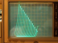
The latest "new" series Schade N Fdbk (UnSet, CED) scheme can produce remarkable "triode" curves. Adjustable from the native triode to 211 like "perfect" triode curves by setting how much Schade N Fdbk is used. Curves for an ordinary TV "Sweep" with the "new" series Schade below.
I see where the %UL alters the effective output impedance of the triode formed. Matching that Z would maximize power transfer for a given B+ I guess, but only if the tube can deliver that power level within its dissipation and current limits. No point in lowering the load Z to get a match if the tube can't deliver. That would just make for more distortion.
For distortion purposes, one generally likes to see 3 to 5 X the effective triode Rp for the load, which would be a much higher OT impedance. Maybe not practical or too high a B+ required.
All I can say is that it maybe provides some additional boundaries to the design process. What purpose are you trying to achieve?
I guess I would look at the effective triode Rp versus the load Z to see if one could actually achieve the low distortion guideline (3x to 5x). If not, then some additional N Fdbk around the driver stage would be needed to get the effective triode Rp down well below the load Z for sufficiently minimized distortion.
One issue with the UL scheme is that it cannot improve the effective triode performance beyond what the native internal triode curves look like. There could still be excessive plate curve rollover for example from a grid1 spaced too close to the cathode (causing 2nd H dist.). Exterior (linear) N Fdbk can of course improve beyond those internal triode characteristics.
The latest "new" series Schade N Fdbk (UnSet, CED) scheme can produce remarkable "triode" curves. Adjustable from the native triode to 211 like "perfect" triode curves by setting how much Schade N Fdbk is used. Curves for an ordinary TV "Sweep" with the "new" series Schade below.
Attachments
Last edited:
I've one EL34 based amp with 43% UL ( improvements on 12AX7 12AT7 EL34 schematic? ) and I'm building an EL84 Baby Huey with 23% UL taps and shunt feedback, and I'm trying to find ways to optimize them.
The UL N Fdbk uses up quite a bit of the output tube's gain, so not so much is left over for Shunt "Schade" N Fdbk to do more. Some simple calculations can give an idea of what is possible, but you may have to go back to the driver stage to get sufficient gain to lower the output effective "triode" Rp enough for low distortion. Only so much can be done using local N Fdbk around the output tube.
Another problem arises with shunt "Schade" local N Fdbk. The feedback resistor from plate to grid is supposed to provide current Fdbk proportional to the output voltage. But it actually provides current proportional to plate V minus grid1 voltage. With low gain this can mean grid1 V is a significant error term there. This is what lead to the "new" series Schade N Fdbk scheme, which avoids this.
Also, conventional N Fdbk to the driver stage avoids the issue too. Higher loop gain leads to less error in the Fdbk current and lower output Z.
A driver loop can provide much more error correction and output impedance lowering than a local loop. Of course, stability is then a bigger issue, but should be manageable if the OT is not in the loop.
Last edited:
Thanks, I sent my previous post before you posted the perfect-triode curves.
It is really ashtonishing. The EL34 amp has a high gain cascoded PI, and I used nfb from the driver and the output of the amp.
The shunt on EL84s is easier to be implemented, because there's only need of around 30 Vpp to drive them. I will see if there will be need of gnfb there.
I've also ordered a very cheap SE kit, just because I had a good coupon for it and for a local toroidal transformer supplier. I will open a dedicated thread to ask your support to implement the improved shunt feedback there.
Oh, woops. Was late last night when I was posting.
The shunt or series type (Schade) local N Fdbks only require gain from the driver, so are still do-able.
For the shunt case though, the UL part requires more grid drive V signal (along with more drive current to fight the shunt current), so it makes the required drive worse and may cause the mentioned distortion to the shunt Fdbk current.
Last edited:
- Status
- This old topic is closed. If you want to reopen this topic, contact a moderator using the "Report Post" button.
- Home
- Amplifiers
- Tubes / Valves
- Adjustable distributed load discussion