I have been VERY slowly building an active crossover/amp using the crossover boards from Bob & Jens, I thought I would include a Rod Elliot signal switch to turn the unit on and off, which I have previously used for a sub. After an unbelievable amount of hours of trying to get the signal switch to work properly (didn't have this issue with the sub) I finally worked out that if I use a linear PSU (tried 3) to power the crossover, when the power is turned off by the signal switch -0.6V DC appears at the signal input of the crossover board (which is connected to the signal switch) and this (I'm as sure as I can be) forces the signal switch to turn back on. If I use a Switching supply to power the crossover no -DC appears at the crossover input and the signal switch works fine.
Obviously I'd like to use a linear supply, has anyone go any thoughts on how to get around this problem?
Obviously I'd like to use a linear supply, has anyone go any thoughts on how to get around this problem?
Disconnect the signal switch from the xo inputs. I bet you find some offset at the switch inputs. You probably have a mismatch in the resistors that make up the virtual ground. The only other thing I can think of is your preamp puts out some DC when off (floating output cap?)
One thing I don't care for with Rod's circuit is his use of the positive inputs for the mixer. This creates crosstalk where the inverting input is a virtual ground so crosstalk is eliminated. If you built the circuit point to point it is fairly easy to rearrange the input and reference voltages to fix this. Otherwise make an inverting buffer/mixer to eliminate crosstalk.
One thing I don't care for with Rod's circuit is his use of the positive inputs for the mixer. This creates crosstalk where the inverting input is a virtual ground so crosstalk is eliminated. If you built the circuit point to point it is fairly easy to rearrange the input and reference voltages to fix this. Otherwise make an inverting buffer/mixer to eliminate crosstalk.
I disconnected the signal input at the xo and left the Squeezebox connected and the signal input to the signal switch connected as before and there is no DC offset at the switch input. From memory the DC offset was present at the xo input (with the linear supply) without the signal switch being connected.
Rod suggests the crosstalk shouldn't be an issue and if necessary on connect one of the inputs.
Rod suggests the crosstalk shouldn't be an issue and if necessary on connect one of the inputs.
If I understand you, there may be a DC ground issue with a source. I've had this with my cable box. Cable ground always seems to be a few tens of mV different than mains ground. After several service calls the ground level kept shifting so I got a cable isolation transformer. The drill is start with nothing connected and add piece by piece until you find the offending component.
I found the crosstalk objectionable with Rod's circuit. Imaging was collapsed. I don't understand why Rod didn't do such an easy fix. When you disconnect one side you lose some gain and may want to adjust so that it triggers in a reasonable time. You may want to do that anyway if you're sensing after your attenuator.
I found the crosstalk objectionable with Rod's circuit. Imaging was collapsed. I don't understand why Rod didn't do such an easy fix. When you disconnect one side you lose some gain and may want to adjust so that it triggers in a reasonable time. You may want to do that anyway if you're sensing after your attenuator.
Bob
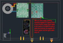
Now I've recovered from a bad case of the flu & am feeling a bit more positive I thought I'd have another go at explaining the issue I'm having with the Signal Switch & thought maybe a diagram would help, see attached. I have deleted a lot of stuff to keep it simple.
Also I have attached a copy of the schematic for the input of the signal switch and was hoping you might be able to explain exactly") what I should do to stop the crosstalk.
what I should do to stop the crosstalk.
Now I've recovered from a bad case of the flu & am feeling a bit more positive I thought I'd have another go at explaining the issue I'm having with the Signal Switch & thought maybe a diagram would help, see attached. I have deleted a lot of stuff to keep it simple.
Also I have attached a copy of the schematic for the input of the signal switch and was hoping you might be able to explain exactly
what I should do to stop the crosstalk.Attachments
You must have a grounding issue with your linear power supply connections. That's the only thing I can think of that would cause the DC at the inputs.
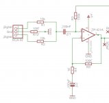
As for converting to inverting inputs, Jumper R4, make C2 100 nF and lift it's ground connection. The formerly grounded connection becomes your inputs - that's where you connect R1 and R2. Increase R5 to ~500K to maintain the gain. You can eliminate C1 and everything to the left and including C1.
You need to have C2 since the switch operates on a single supply, but the idea is to make something like this:
 Note that R3 is your connection from the positive input to the virtual ground that single supply needs.
As for converting to inverting inputs, Jumper R4, make C2 100 nF and lift it's ground connection. The formerly grounded connection becomes your inputs - that's where you connect R1 and R2. Increase R5 to ~500K to maintain the gain. You can eliminate C1 and everything to the left and including C1.
You need to have C2 since the switch operates on a single supply, but the idea is to make something like this:
You must have a grounding issue with your linear power supply connections. That's the only thing I can think of that would cause the DC at the inputs.
As for converting to inverting inputs, Jumper R4, make C2 100 nF and lift it's ground connection. The formerly grounded connection becomes your inputs - that's where you connect R1 and R2. Increase R5 to ~500K to maintain the gain. You can eliminate C1 and everything to the left and including C1.
You need to have C2 since the switch operates on a single supply, but the idea is to make something like this:
Note that R3 is your connection from the positive input to the virtual ground that single supply needs.
Is this what you mean?
Bye the way, thanks
With the linear supply all I can think to do re grounding that would be any different is to connect the DC ground output from the power supply to the star ground at the earth point and connect the crossover power ground to the same point? From the little I know about star grounding I should take every ground directly to the star ground.
Attachments
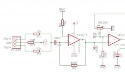
Close, leave R3 connected as in the original circuit - to the "virtual" ground created by R8 and R10. Notice that they create a voltage midpoint between the + supply and ground.
If you reference to ground as shown you create a large voltage difference between the inputs and the output will lock up.
If you reference to ground as shown you create a large voltage difference between the inputs and the output will lock up.
Last edited:
Close, leave R3 connected as in the original circuit - to the "virtual" ground created by R8 and R10. Notice that they create a voltage midpoint between the + supply and ground.
If you reference to ground as shown you create a large voltage difference between the inputs and the output will lock up.
Like this?
Obviously with this setup there is no connection to ground for the inverting input of TP-IC1 which I assume is ok?
Attachments
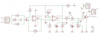
That's it. Yes, no resistor directly to ground from the negative input. That's standard inverting opamp configuration. Ground return to the negative input is through the feedback connection and the source.
It was fairly easy to modify the PCB's I had made and I'm glad to say the changes work
. I haven't tried it with the linear supply yet but will do. It will be a few weeks before I get to test the sound, can't what it's been a long haul this project.
With the R5 resistor that was increased to 510K which way do I go resistance wise to increase sensitivity?
Many thanks
Bob
I know I'm way OT but I thought you'd probably like to know the result of your advice. As mentioned earlier the revised signal switch worked with the SMPS so tonight I installed the linear supply as before & got exactly the same result that the signal switch wouldn't turn off. I reconfigured the grounding for the linear PSU and the things its powering at the moment by running the ground from the linear PSU output directly to the Ground/Earth point and then ran the crossover and speaker protection board power grounds directly to the Ground/Earth point (Star ground I guess) and low and behold it worked well at least for today
I should get to test the new speakers with the crossover in the coming weeks and then I'll have to adjust the crossover filters as required to get the sound right, which means you'll probably hear from me again
Many thanks,
I know I'm way OT but I thought you'd probably like to know the result of your advice. As mentioned earlier the revised signal switch worked with the SMPS so tonight I installed the linear supply as before & got exactly the same result that the signal switch wouldn't turn off. I reconfigured the grounding for the linear PSU and the things its powering at the moment by running the ground from the linear PSU output directly to the Ground/Earth point and then ran the crossover and speaker protection board power grounds directly to the Ground/Earth point (Star ground I guess) and low and behold it worked
well at least for today I should get to test the new speakers with the crossover in the coming weeks and then I'll have to adjust the crossover filters as required to get the sound right, which means you'll probably hear from me again
Many thanks,
Attachments
Last edited:
Hooray for star grounds!
A friend demonstrated ground loops in a high power RF amp by soldering a 22 gauge wire to the chassis, running it up an inch, horizontal for 8" and then soldering it to another point on the chassis. Using a screwdriver he was able to pull an arc from the middle 2/3 of the wire to the chassis.
A friend demonstrated ground loops in a high power RF amp by soldering a 22 gauge wire to the chassis, running it up an inch, horizontal for 8" and then soldering it to another point on the chassis. Using a screwdriver he was able to pull an arc from the middle 2/3 of the wire to the chassis.
- Status
- This old topic is closed. If you want to reopen this topic, contact a moderator using the "Report Post" button.
- Home
- Group Buys
- Active filter board GB