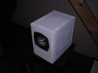
Business end of the bass module. The upper tube is the short tube, and the lower tube is the long tube. Tuning points are 168 Hz and 52 Hz respectively. It's not your imagination -- the lower terminus is slightly smaller than the upper terminus. This was a mistake.
Attachments
More:
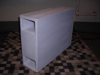
Another note -- this thing is quite efficient. The driver used has an efficiency of 83dB at 2.83v, and each Tang Band driver is 86dB (1w/1m) efficient, yet the Wave Cannon principle easily makes up the difference, and the system is nicely matched. Adding or removing stuffing from the upper and lower lines allows level matching through different parts of the passband, and can bring the overall level of the Cannon down to the level of the satellite speakers as well as smoothing the response. I used 3 handfuls of polyfill in the upper tube at the driver end, and then 2 handfuls of polyfill in the last bend of the lower tube (opposite the terminus). The driver is in the top rear of the enclosure, firing downward into the longer tube. The passive crossover networks (one for each channel) are directly below the driver, in the first section of the long tube. They don't seem to obstruct the tube.
While auditioning this system, I had the bass module behind the TV stand, firing into the corner. I only brought it out for the "money shot" of the entire system. Localization is a problem if proper placement of the module is not taken into consideration. For their Acoustimass modules, Bose recommends placing them along the front wall, firing parallel to the wall, across the front soundstage. This seems to work well with my bass module as well. A good way to describe the sound is that it sounds like a decent multimedia subwoofer, like some of those that are currently being distributed with multimedia speaker systems. There is some distortion happening, and the waveguide just takes those effects and boosts them just like they were the program itself. That's a fair disappointment when it comes to building something for hi-fi use, but this is more for casual listening.
I think I'll have to design a new crossover for the system. The bass module is getting way too much midrange leakage, and the resonant lines don't provide much of a lowpass effect. I've added stuffing to the upper and lower lines (less stuffing to the longer line) to try to "damp out" the midrange which has leaked into the woofer, but it's just no substitute for an updated crossover. Perhaps a Linkwitz-Riley second order network is needed. I have a cell-phone picture of the woofer taken while I was applying glue to the cone (to stiffen it for woofer duty). I'll see about getting that posted up here.
Perhaps you can change the shortest tube into a basreflex much like the highest tuned part of a 6th order BP? Also with a Fs of 107 Hz it sounds like the low end mostly depends on the resonant frequency of the longest tube, hence the resonant-like sound. While the driver by nature does focus on the midrange which you don't want?
Wkr Johan
Wkr Johan
One of the design criteria for this type of waveguide virtually dictates a driver with a much higher Fs than would typically be considered. I think that it has to do with mass-loading of both the sides of the diaphragm. The patent prescribes a Long Tube that is equal to 1/2 WL of Fs, and a Short Tube that is one-third the length of the Long Tube. I wasn't concerned with true subwoofer output from a 4" driver, so I decided that response from 40 to 180 Hz would be appropriate for the application. Unfortunately, my first-order filter doesn't do enough filtering, so I'm going to re-design the crossover around a second-order network at a lower corner frequency. The resulting crossover board will be as long as it possibly can, in order to fit all the components I will need, since I can't get 14mH inductors and need to use two 7mH inductors in series. That means eight inductors for the entire two-channel, two-way filter network.
I'm aware that the actual Wave Cannon uses a 12" woofer. The Bose Acoustic Wave Music System uses a 4.5" woofer in a similarly-designed line. My project is similar to the low frequency section in the Acoustic Wave Music System, except that mine uses a slightly smaller driver. But according to the theory, this thing should perform well. And it does, but the resonant line has modes in the midbass as well as the low frequencies, which necessitate a higher-order crossover especially in a bass module application.
Though I'm also experimenting with the Daline concept in a small subwoofer for my parents using the Tang Band W5-1138SG 5.25" long-excursion mini-subwoofer. That project should be coming to fruition in about a week or so from now. I'll be interested to hear how the Decoupled Antiresonant Line concept compares to a typical vented reflex box. That driver, at the limits of its linear travel, sweeps as much air as an 8" woofer with 3.5mm Xmax. But its output should be augmented by the antiresonant line to an even greater degree than it would be by a reflex vent.
Though I'm also experimenting with the Daline concept in a small subwoofer for my parents using the Tang Band W5-1138SG 5.25" long-excursion mini-subwoofer. That project should be coming to fruition in about a week or so from now. I'll be interested to hear how the Decoupled Antiresonant Line concept compares to a typical vented reflex box. That driver, at the limits of its linear travel, sweeps as much air as an 8" woofer with 3.5mm Xmax. But its output should be augmented by the antiresonant line to an even greater degree than it would be by a reflex vent.
Perhaps you can change the shortest tube into a basreflex much like the highest tuned part of a 6th order BP?
There actually exists a Yamaha patent that the opposite: A bandpass using a quarterwave-resonator for the uper tuning and a reflex box for the lower one.
Regards
Charles
BAM said:Though I'm also experimenting with the Daline concept in a small subwoofer for my parents using the Tang Band W5-1138SG 5.25" long-excursion mini-subwoofer. That project should be coming to fruition in about a week or so from now.
BAM: did u get a chance to build the sub with W5-1138?, I want to build one with the same speaker, but no information on the cabinet/amp details.
thanks,
gychang
regarding the straight cannon - look at this sim's offset (its late - what did I do wrong?)
http://img83.imageshack.us/img83/5827/huhne0.jpg
how does one build an effective half-square sub?
http://img83.imageshack.us/img83/5827/huhne0.jpg
how does one build an effective half-square sub?
Greets!
You didn't sim a BWC, but a straight TL with the driver off-set ~1/3 from the closed end.
WRT the 1/2 square pipe, here's my response to Morey James awhile back:
When you mentioned DJK's analogy of the BWC being based on 'half square' antenna theory/85 Hz driver example recently, I just accepted it at face value due to who said it and answered your Qs based on the info presented without doing any research.
Since you keep bringing it up though, I did a bit of 'due diligence' and not surprisingly it does indeed conform to 1/2 square antenna folding requirements with the short pipe being 1/4 the total pipe's 1 WL length (Fp) and with 1/4 - 1/2 - 1/4 WL fold spacing, or in this case, 170, 340, (2) 680 Hz respectively.
Anyway, it's not a good idea IMO to think of a resonant pipe folding scheme in these terms, and especially as 1/8-1/4-1/8 WLs, so let's pick the BWC apart to hopefully get a better 'feel' for these things and how he arrived at his alignment.
The BWC is a nominally two octave bandpass (BP) device consisting of two 1/4 WL pipes attached to the driver that are 3 ft (36") and 9 ft (108") long, so using your 13,489.5"/sec SoS:
total pipe length = Fp = 13489.5/4/(36+108) = 23.42 Hz
The patent notes that a smoother performance can be had by using a driver that has a Fs = 1/2 WL of the total tube length (Fp), so ideally its Fs = 13489.5/2/144 = 46.84 Hz, or 2*Fp.
The patent refers to the short, long pipes as 1/4 WL and 3/4 WL that sum to 1 WL since it has a 1:3 pipe length ratio, but we're dealing with a 1/4 WL system, so in reality:
1/4 WL short front pipe = (1/4*1/4) = 1/16 WL of Fp = 13489.5/16/23.42 = 36"
Fh = 13489.5/4/36 = 93.68 Hz
1/4 WL long rear pipe = (1/4*4/3) = 3/16 WL of Fp = 13489.5/5.333/23.42 = 108"
Fl = 13489.5/4/108 = 31.22 Hz
Making the resonant 'chain': ~23.42, 31.22, 46.84, 93.68 Hz, with 0.415/0.585/1.000 octave spreads for this straight BWC, or a two octave bandpass (BP) alignment centered on the driver's Fs.
Enhancing it with 'half square' antenna folding:
For smoothest response/broadband gain we want the two openings 1/2 WL of the total pipe length (Fp) apart = (1/2*1/4) = 1/8 WL of Fp:
13489.5/8/23.42 = 72"
13489.5/72 = 187.36 Hz
Since it's 144" long, the 'legs' will be (144-72)/2 = 36" long.
Rounding out our resonant 'chain': ~23.42, 31.22, 46.84, 93.68, 187.36 Hz, we wind up with 0.415/0.585/1.000/1.000 octave spreads.
Viewed by some others, this would be a 13489.5/2/72 = 93.68 Hz 1/2 WL beam with two 93.68 Hz 1/4 WL 'legs', which seems to me a totally wrong way to describe these since it does nothing but confuse/mis-inform folks who aren't already at least somewhat familiar with the two distinctly different systems. As always though, YMMV.
OK, in light of the above, let's see if DJK's 85 Hz 4" driver pipe design conforms with a 40" 'beam' and 20" 'legs':
total pipe length = Fp = 13489.5/2/85 = 79.35"
Looks like we need a SoS adjustment: 80"/79.35" = 1.0082*13489.5" = 13,600":
total pipe length = 13600/2/85 = 80"
Fp = 13600/4/80 = 42.5 Hz
short pipe = 13600/16/42.5 = 20"
Fh = 13600/4/20 = 170 Hz
long pipe = 13600/5.333/42.5 = 60"
Fl = 13600/4/60 = 56.67 Hz
1/2 WL 'legs' spacing = 13600/8/42.5 = 40"
13600/40 = 340 Hz
Since it's 80" long, the 'legs' will be (80-40)/2 = 20" long.
Making the resonant 'chain': ~42.5, 56.67, 85, 170, 340 Hz, with 0.415/0.585/1.000/1.000 octave spreads.
Works for me, so substitute whatever SoS and driver Fs you prefer, or if you want a particular BW, then choose the driver Fs that most closely is either one or two octaves (if folded) below Fh and figure the rest.
Of course these are all heavily rounded off dims since the bend lengths, driver cab Vb, and end corrections aren't factored in, but it's close enough for an inexpensive computer system or true sub duty that's below our acute hearing BW. With one octave resonant spreads in the mids of this alignment though, adding the folds for the extra BW doesn't seem like a good plan to me, but as always, YMMV.
GM
Greets!
Like with LspCad, I don't see a way to do it since we can't remove the chambers and just see the vent pipe's output.
It would depend on having the right driver for the job since the horn could be at a higher CR, yielding a greater power handling efficiency. An optimized tapped horn appears to be the hand's down winner.
GM
hey GM - theres not enuff mobililty yet in these things to have real fun. - I'm trying to figure out where AJ works and where it don't
way OT -can LSP extimate a K's low end as bp/whatever? - like to take PYM1298 lower but might be a futile exercise - I'd like something capabile of being obnoxiously loud without having obnoxious tone - hahaha - might take midrange - oh - might unity type work squished down in height aspect with only two mid drivers?
1298 ~TS ~95oz magnet, 3" coil
Re=5.2
Fs=46.29
qes=0.29
qms=5.69
Vas=113.85
Sd=519.45
xmax=3.2
btw - 206 Fostex sims so I might officially join FR(?) if AJ is correct then theres a "broad peak" (oxymoron?) with the Sammi when no damping
undamped IMF-8 t-line 3-drivers
http://img208.imageshack.us/img208/7941/imf813drvyl6.jpg
206E BLH vs damped t-line
http://img254.imageshack.us/img254/984/blhvstl206at7.jpg
way OT -can LSP extimate a K's low end as bp/whatever? - like to take PYM1298 lower but might be a futile exercise - I'd like something capabile of being obnoxiously loud without having obnoxious tone - hahaha - might take midrange - oh - might unity type work squished down in height aspect with only two mid drivers?
1298 ~TS ~95oz magnet, 3" coil
Re=5.2
Fs=46.29
qes=0.29
qms=5.69
Vas=113.85
Sd=519.45
xmax=3.2
An externally hosted image should be here but it was not working when we last tested it.
btw - 206 Fostex sims so I might officially join FR(?) if AJ is correct then theres a "broad peak" (oxymoron?) with the Sammi when no damping
undamped IMF-8 t-line 3-drivers
http://img208.imageshack.us/img208/7941/imf813drvyl6.jpg
206E BLH vs damped t-line
http://img254.imageshack.us/img254/984/blhvstl206at7.jpg
Acoustic Wave Cannon
Hi,
This started with a simple question of "Hi
Does any body have an idea how to build a bass canon (like the bose)"
I've learned a lot reading the replies but as a novice am still short of some details.
I am looking to build a wave canon for fun and to use at my annual summer BBQ. I usually use some old Infinity speakers and an old Pioneer receiver and can rock the block. This year an added bit of base would be cool. I'd drive it with a second amp.
So you see I'm low tech by your standards. And I'm trying to do this on the cheap mostly for fun and if it works the shock value.
I have laying around 2 Bazooka EL1004 ten inch subwoofer speakers and 2 twelve inch sony woofers (from who knows where). I don't have the stats.
I'd like to use some sonus tube (concrete construction forms) as the barrel. They come in 12 and 10 inch with and are 4 ft long. I can connect and get 4, 8, 12, or 16 ft length. The plan is to either use duct tape or screws so I can take it apart and put it in the garage next year.
If I follow your comments all I pretty much need to do is put the driver in 1/4 of the way, wire it and go.
What am I missing?
Is 12 ft enough or do I need 16 ft?
If I start with the 12 in drivers and later make a wood plug to fit the 10 inch will that be ok?
And lastly if I hook both sets of wires from the AMP to one speaker will I be OK?
See low tech and low knowledge but willing to learn.
You can actually just put the woofer on the end of a tube tuned to 1/4 the wavelength that you want, let's say 30Hz. That would seriously rock the yard!
You can use two cannons next to each other with one woofer wired out of phase and on the other side than the other "paired" cannon. KISS-don't over think it!
The Bose idea just smoothed things out in the upper band of the operating range of the canon, if you have speakers that can already hit 80Hz-120Hz cleanly you are just fine!
I was somewhat disappointed with the outcome of my experimental wave-cannon bass module. I found that it needed a good deal of EQ to reach the lowest notes of its range with the same authority that it handled the upper end, and woofer excursion was a problem.
I've got a hypothesis, though. I think that it may actually be better to use a driver where the Fs of the driver is equal to the 1/4-wave frequency of the longer of the two tubes. This way, there will be quarter-wave loading of the driver diaphragm and some additional output down near the bottom of the cannon's range. I'm thinking of using the Aurasound 4" incredibly-high-excursion woofer, but Madisound is out of them, so I'll need to find another source. I contacted Madisound, and they said Aurasound recently stopped production of the drivers, but there had been rumors that production could restart in a few months. I think this particular driver will be the answer for my little wave cannon.
------
(Formerly known as BAM)
- Status
- This old topic is closed. If you want to reopen this topic, contact a moderator using the "Report Post" button.
- Home
- Loudspeakers
- Subwoofers
- Acoustic wave canon