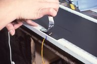
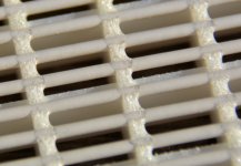
I've attached a photo of the bias wire being installed. The black area is the conductive coating, and as you can see, the stripped end of the bias wire is secured with a piece of foil tape to hold it in place while the two halves of the panel get glued together.
And therein lies the problem. Acoustat panels are glued together, and are not meant to be disassembled. It is possible to pry the two halves apart, but you stand a very good chance (probably about 98%) of damaging the Mylar diaphragm in the process. Ordinarily, this panel would be considered trash.
Since you have nothing to lose, I suppose you could try disassembling the panel. Perhaps some else has some experience with this. Being a factory guy, my only experience was to throw away the panel and replace it with a new one. We never bothered trying to repair panels.
The original wire was custom made, with PVC insulation tested for 10kV. Any wire with a suitable voltage rating would be okay, but unfortunately the type of wire is the least of your troubles. Sorry I can't be of more assistance .
.
And therein lies the problem. Acoustat panels are glued together, and are not meant to be disassembled. It is possible to pry the two halves apart, but you stand a very good chance (probably about 98%) of damaging the Mylar diaphragm in the process. Ordinarily, this panel would be considered trash.
Since you have nothing to lose, I suppose you could try disassembling the panel. Perhaps some else has some experience with this. Being a factory guy, my only experience was to throw away the panel and replace it with a new one. We never bothered trying to repair panels.
The original wire was custom made, with PVC insulation tested for 10kV. Any wire with a suitable voltage rating would be okay, but unfortunately the type of wire is the least of your troubles. Sorry I can't be of more assistance
.Attachments
super help needed now I have just found a hole in one of the 2+2 acoustat panels its about the size of a grid square any options at all? finding a replacement panel in NZ is impossible can I just snip the wire and run 3 panels can anyone tell me how to take panels apart and is this difficult?
also after vacuuming warm air blowing staring, glaring ignoring yelling cursing and threatening the rubbish bin one of the other panels isnt working either any suggestions there?
Are you sure the 'hole' is actually in the Mylar diaphragm, and not just a void in the conductive coating? A void in the coating would appear as a clear spot.
If there truly is a hole in a diaphragm, was it produced by excessive heat, or is it a tear? If it's a tear, the problem will only get worse and will probably cause a rattling or buzzing sound. As mentioned in the previous post, the panels are glued together and aren't made to be repaired. On the other hand, if the hole is melted, you can probably continue to use the panel with little or no change in performance. This last comment is a prediction, and not based on experience: I've never used a panel with a hole in the diaphragm.
Yes, you can disconnect that one affected panel, but this would have an adverse effect on the performance, and you would probably be very unhappy with the result.
Panels do appear periodically on eBay and other venues, so you might try buying a replacement there.
I have Acoustat panels with holes..... playing now ...have been playing
5 years...... from excessive heat....that like andy said....burn all the edges so don't get biger...............but then I have had tears....were the nut driver slipet
... hit the mylar......never got any bigger an plays fine..........can you hear any diff? ......I cant......I have had minny esl panels....Acoustat an others....
now on the other panels not working................unplug the Ac.....look in the interface box...
I bet one of the wire have broke off at the board........if these are 3s.....
.the bias should have 3 wires....................3 wires yello.... 3 blue... go to the board .....
here a pic the board should be the same
Attachments
![427682d1404861109-acoustat-answer-man-here-air[1].jpg](/community/data/attachments/429/429052-f81b3ea18d3d239e2e189891482b30b1.jpg)
super help needed now I have just found a hole in one of the 2+2 acoustat panels its about the size of a grid square any options at all? finding a replacement panel in NZ is impossible can I just snip the wire and run 3 panels can anyone tell me how to take panels apart and is this difficult?
also after vacuuming warm air blowing staring, glaring ignoring yelling cursing and threatening the rubbish bin one of the other panels isnt working either any suggestions there?
All of the old Acoustat panels that I ever seen have many small pinholes in the mylar which I assume are from being driven hard and arcing. I've never noticed any issues with the sound from these, however I don't have any panels without the holes to compare them to. A hole the size of a grid square is pretty big hole, however, so it may be more of an issue.
Take care,
Doug
Are you sure these 'holes' are not just tiny voids in the conductive coating? Remember that the Mylar is clear, so that a void in the black coating will allow light to pass through the diaphragm, which could appear as a hole. Such voids are common and of no consequence. However, with the high-resistivity conductive coating used by Acoustat, and the extremely high bias power supply output impedance (>500 Mohm) destructive arcing should be virtually impossible.
A difference in volume between the speakers usually indicates a problem in the 5000-volt bias power supply. I would suggest first replacing all five of the capacitors in the voltage multiplier. These are 3300 pF, 3000-volt ceramic discs. A higher voltage rating is okay as long as they fit okay in the board. I also suggest replacing these parts in both interfaces. There's no point in using fancy "audiophile grade" parts in this application - plain ol' ceramic discs are fine.
If that does not solve the problem, the next step is to replace all five of the high voltage diodes (again, in both speakers). The original manufacturer no longer makes this part, but substitutes are available. The minimum rating is 10,000-volts at 25 milliamps. Higher ratings on either voltage or current are okay, as long as they fit the board. Note that these diodes cannot be tested like a regular diode with an ohmmeter, as they are a stacked multiple-junction type.
The original grille cloth is a double-knit polyester weave, chosen for reasonable sonic transparency and the ability to hide the innards of the speaker. If you don't mind seeing through the cloth a little bit, a single knit fabric is a better choice, preferably with some stretchiness so that the tube of fabric will conform to the shape of the speaker. Perhaps some other members can share their experience on replacement grille fabric.
I have a pr of 1+1s that I suspect need bias ps rebuilt. The last time I listened to them they sounded weak and one much weaker.
I can source the caps in the multiplier but the diodes I haven't a clue. What is a suitable replacement? Or, is it possible to stack 1N40XX diodes?
Also, does anyone have plans for a HV probe we can use to accurately measure the bias?
I really miss listening the them.
This was a number of years ago, so I can't say for sure. However, I did disassemble the panel with the plastic/glue drip that was causing the buzzing vibration, and I think that I would have noticed that they were just voids in the coating and not actual holes.
If I get a chance I'll have another look at that panel and confirm this either way.
Take care,
Doug
If I get a chance I'll have another look at that panel and confirm this either way.
Take care,
Doug
I have a pr of 1+1s that I suspect need bias ps rebuilt. The last time I listened to them they sounded weak and one much weaker.
I can source the caps in the multiplier but the diodes I haven't a clue. What is a suitable replacement? Or, is it possible to stack 1N40XX diodes?
Also, does anyone have plans for a HV probe we can use to accurately measure the bias?
I really miss listening the them.
Although it is possible, I wouldn't recommend stacking 1N400X diodes. You can't guarantee that the voltage will divide equally among the series-connected diodes. Try contacting HV Components Associates, www.hvca.com. They made the original diodes, but that p/n has been discontinued. Their current line has a p/n G10FS that should be a suitable replacement. I don't know what their policy is regarding minimum order etc.
Of course, any diode with a suitable voltage and current rating is fine, but most of the ones available have a higher current rating and are physically too large to neatly fit on the board.
Although a high voltage probe is the preferred and safer method of measuring the bias voltage, you can also use an ordinary digital voltmeter with a 10-megohm input impedance, provided that you measure the voltage ONLY after the 500-Mohm resistor (that is, at the red socket where the speaker connects). Attempts to measure anywhere else in the circuit will likely ruin your meter.
In this situation, the 500-Mohm resistor and the input impedance of the meter creates a voltage divider, and you will measure only a fraction of the actual voltage. Firmly connect the negative lead of the meter to chassis ground, and the positive lead to the red socket after the supply has had a few moments to charge up. You will measure in the range of 70-80 volts for a properly working bias supply. Naturally, if your meter has a different input impedance, the voltage division will change and you will get a different reading. And, I will make the disclaimer that this method is suitable only for factory-stock bias supplies. Any modifications to the circuit may effect the reading and/or ruin your meter.
Let us know how you make out with HV Components. I'm sure other Acoustat owners would be interested in that information. Also, feel free to post the type and vendor for the capacitors. There is no advantage in using anything but the original type ceramic discs of the same capacitance and equal or higher voltage rating.
This was a number of years ago, so I can't say for sure. However, I did disassemble the panel with the plastic/glue drip that was causing the buzzing vibration, and I think that I would have noticed that they were just voids in the coating and not actual holes.
If I get a chance I'll have another look at that panel and confirm this either way.
Take care,
Doug
There has been some discussion recently about how to repair a missing bias feed wire. My stock answer is that the panels are not meant to be taken apart (which is true enough) and that any attempts to do so would likely ruin the diaphragm. It might be of value to the Acoustat Community if you could write about your experience and methods with panel dis-assembly and re-assembly. This is something we would have never bothered with at the factory, so I have no experience to share. Thanks.
I have had good experience with the GP02-40 4kV diodes made by Vishay, stocked by Mouser.I can source the caps in the multiplier but the diodes I haven't a clue. What is a suitable replacement? Or, is it possible to stack 1N40XX diodes?
The 4kV rating is double the recommended rating by Vishay in their application note for a multiplier circuit like the Acoustat.
GP02-40-E3/54 Vishay Semiconductors | Mouser
AN - Using Rectifiers in Voltage Multiplier Circuits
I have had good experience with the GP02-40 4kV diodes made by Vishay, stocked by Mouser.
The 4kV rating is double the recommended rating by Vishay in their application note for a multiplier circuit like the Acoustat.
GP02-40-E3/54 Vishay Semiconductors | Mouser
AN - Using Rectifiers in Voltage Multiplier Circuits
Excellent information Bolserst! Although this diode's PIV rating of 4-kV is less than the original diodes rating of 10-kV, I agree that it is quite suitable for the Acoustat bias supply, as the supply runs 'only' about 1-kV per stage. And the price is right: only about 15 cents each in batches of ten. I don't remember what Acoustat paid for the original diode, but I can assure you it was a lot more than 15 cents even in much greater quantity!
Acoustat's choice of diode was a case of overkill on the voltage rating, but perhaps the choices were limited in the early 80's when that part was spec'd into the design.
There has been some discussion recently about how to repair a missing bias feed wire. My stock answer is that the panels are not meant to be taken apart (which is true enough) and that any attempts to do so would likely ruin the diaphragm. It might be of value to the Acoustat Community if you could write about your experience and methods with panel dis-assembly and re-assembly. This is something we would have never bothered with at the factory, so I have no experience to share. Thanks.
Well I can tell you how to take apart a panel, but reassembling one and having it function again is something that I haven't tried.
When I tried to repair the "buzzing" panel that I mentioned before, the first thing that I did was very carefully examine it from top to bottom, looking for loose wires, debris, or any damage to the area of the panel that I could see through the wires. I removed the felt dampers from the back side and checked there as well. Finding nothing, I cleaned out the panel with compressed air and retensioned the membrane with heat, without success.
While examining the membrane while it was backlit, I noticed that I could see many pinholes throughout, so I checked the panels in both my model 2s and 1+1s and found them to be the same.
Still hoping to fix the panel, I again thoroughly examined, cleaned, and retensioned, but the buzzing remained. Finally, when I was yet again trying to retension the membrane, I got it a tiny bit too hot and a few small holes formed, the largest being about 2 mm. At this point I decided I had little to lose by disassembling the panel.
I very carefully pried the panel apart, but as careful as I was some of the plastic frame was broken and in a couple of tiny places the mylar tore away from the frame, leaving two 1mm X 6mm gaps right at the edge of the diaphragm.
I then had a close look at the inside of the panel trying to find the cause of the original buzzing issue and found a small drip of glue sticking out from the stator wires towards the membrane. This drip had apparently formed when the wires were first attached and had been there ever since.
The panel may have been salvageable if there was just the membrane holes, but I doubt that the plastic frame could be properly glued together again with all of the damage. If a person was extremely careful and very lucky they might be able to take a panel apart without damaging it too much for it to be reassembled, but it certainly would be a challenge. Gluing it all back together again would also be a tricky thing to do, but would probably be a bit easier than taking it apart. I think that if I was trying to fix a missing bias feed wire I would do it without actually disassembling the panel. Instead I would try just removing enough of the plastic frame around the connection point to reattach it, and then repair what I removed with some new plastic and glue.
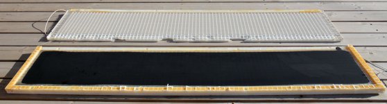
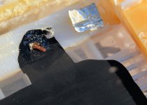
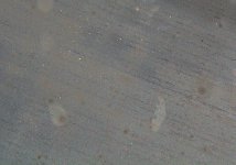
I've attached a picture of the two halves of the disassembled panel, as well as a close-up of the area where the wire is attached to the membrane. The silver metal foil was originally glued on top of the wire attachment point. The third picture shows the pinholes on the membrane, which I can confirm are just damage to the conductive coating and are not actual holes in the mylar. You can also see marks on the membrane from the stator wires, possibly from dust or perhaps from actually "slapping" against the stators. The last picture shows the stator wires glued to the plastic frames. The drip that caused all of the problems was composed of that same clear bubbly glue that holds the wires in place.
Attachments
Well I can tell you how to take apart a panel, but reassembling one and having it function again is something that I haven't tried....
Thanks for your detailed answer. Unfortunately, the end result was just as I have always believed. So I guess I will continue saying that the Acoustat panel is unrepairable until someone comes up with a 'magic' solution. Good things the panels are normally quite reliable and don't require much attention.
Thought I might share my experience in which my panels disassembled themselves.
Not sure of the mechanism, age, uv, climate, or whatever, but 12 years ago 2 of my 6 panels separated between diaphragm and rear grid spacers. Much stress and a bit of contact adhesive and I put them back together. Used them for a couple of years and then put them back into storage, out of the frames.
18 months ago tried to reinstall them only to find all had separated. Sourced replacement panels, but still assembling new frames!
Will probably get back to doing something with the old panels one day.
Regards
Gn
this pic from post 1296..
I think most of us that have owned minny older Acoustat panels....have had at lest 1 come apart......
there are also info in post 1296 that looks like this guy mspc....... had found a way to rework the panels.......... put them back togather............ here is info from his post.....
an it sound like one way that worked..
"The speakers can be upgraded to repair most of the problems, a thinner diaphragm can be installed, a lighter conductive material can be used on the diaphragm, a pure copper charge ring can be installed around the diaphragm, you can break up the diaphragm to eliminate the single large “drum-head” resonance, (make the speaker as close to a Sound Lab as possible)"
Please do not tell me this is pure BS because I do this for $150 per panel, I put in all the upgrades that I have mentioned, I repair/upgrade the existing panel WITHOUT building a new one. I then bolt the speaker back together (not easy thing to do it requires adapted tools and is a slow process to get them inside the half inch holes) this allows a mechanical way to hold the diaphragm as well as enhance the hold of the adhesive. The second thing it does is allow any upgrades/repair that may need to be done in the future. Now if this is pure BS that means there is income that I do not need to report to the IRS I will include a statement from you reassuring them that I cannot do this because you said so, therefore they need to ignore those invoices.
As to all the info from these other sites.........take it like all info... with a grain of salt...............
I think most of us that have owned minny older Acoustat panels....have had at lest 1 come apart......
there are also info in post 1296 that looks like this guy mspc....... had found a way to rework the panels.......... put them back togather............ here is info from his post.....
an it sound like one way that worked..
"The speakers can be upgraded to repair most of the problems, a thinner diaphragm can be installed, a lighter conductive material can be used on the diaphragm, a pure copper charge ring can be installed around the diaphragm, you can break up the diaphragm to eliminate the single large “drum-head” resonance, (make the speaker as close to a Sound Lab as possible)"
Please do not tell me this is pure BS because I do this for $150 per panel, I put in all the upgrades that I have mentioned, I repair/upgrade the existing panel WITHOUT building a new one. I then bolt the speaker back together (not easy thing to do it requires adapted tools and is a slow process to get them inside the half inch holes) this allows a mechanical way to hold the diaphragm as well as enhance the hold of the adhesive. The second thing it does is allow any upgrades/repair that may need to be done in the future. Now if this is pure BS that means there is income that I do not need to report to the IRS
I will include a statement from you reassuring them that I cannot do this because you said so, therefore they need to ignore those invoices.As to all the info from these other sites.........take it like all info... with a grain of salt...............
Attachments
![Acoustat%20pics[1].jpg](/community/data/attachments/440/440673-cbd7e1615146187627eb14ab839c1bd5.jpg)
Hi guys!
I am looking to change the speaker binding posts on my Spectra 22 as some of them are striped.
Can anyone recommend new binding posts that with easily fit into the existing holes in the interface box. I am not much of a DIYer and are looking for an easy fix.
Thanks.
I am looking to change the speaker binding posts on my Spectra 22 as some of them are striped.
Can anyone recommend new binding posts that with easily fit into the existing holes in the interface box. I am not much of a DIYer and are looking for an easy fix.
Thanks.
Is it not possible to build 'Acoustat' panels? Back years ago a good friend of mine was a rep for the company that purchased Acoustat. He knew I owned a pair and when he told me the panels were made from common light louvers I was kinda shocked. I dropped a sock and was surprised how simple it appeared.
So, I guess the question is "what is not available to DIY panels"?
The mylar, the coating, stator wires??? I believe I've seen the plastic louvers at the hardware store.
So, I guess the question is "what is not available to DIY panels"?
The mylar, the coating, stator wires??? I believe I've seen the plastic louvers at the hardware store.
The louvers are easy. The combs for the wires would have to be fabricated. Also the frame for the film, but that's much easier. Film, coating, and that's pretty much it. I rebuilt some Acoustat panels (changed diaphragm material) and one day, I'll get around to re-rebuilding since the ones I made were modified by the fingers of a curious 5 year old. At the moment, I don't have a suitable room, so it's a VERY backburnered project.
Hi guys!
I am looking to change the speaker binding posts on my Spectra 22 as some of them are striped.
Can anyone recommend new binding posts that with easily fit into the existing holes in the interface box. I am not much of a DIYer and are looking for an easy fix.
Thanks.
If memory serves correctly, the original binding posts were made by Superior Electric. The main criteria for replacement is that the post fits into the same D-shaped (or was it double-D?) hole, and that the threaded terminal on the back is the same length and thread size as the original. This way the posts will mate to the standoffs inside the enclosure, which in turn connect to the PC board. I think Acoustat cut off the solder-terminal on the end of the post before screwing on the standoffs so that it wouldn't bottom-out inside the standoff.
this pic from post 1296..
I think most of us that have owned minny older Acoustat panels....have had at lest 1 come apart......
there are also info in post 1296 that looks like this guy mspc....... had found a way to rework the panels.......... put them back togather............ here is info from his post.....
an it sound like one way that worked.....
This is all fine and good, and probably creates an acceptable repair if not an actual upgrade. But alas, I fear this is way beyond the capability of the average Acoustat owner who has a problem with panels. And there certainly isn't enough detail provided here for anyone to follow as a 'recipe' for panel repair.
- Home
- Loudspeakers
- Planars & Exotics
- Acoustat Answer Man is here