I am still trying to get my Acoustat Spectra 1100's to work. I did the bias adjustment. I did the 2nd method for testing the voltage. It came out to 8.1 volts at the red ESL terminal. Andy's documentations says I should be getting 75 volts at this point. This means I am getting approx 600 volts. (It should be at 5000 volts). This makes sense because the volume of the speakers seems to be 1/10 of what it should be. I did get a little more volume when I did the bias adjustment. How can I get more? (speak to me like the amatuer I am). Thank you to everyone on this forum")
Are you certain that you have the proper 12-15 volt AC (not DC) wall transformer properly connected to the speaker and to a always-live outlet?
There is a possibility you have an earlier version of the ultrasonic bias power supply that exhibits reliability problems. This is very easy to fix. To determine if you have the earlier supply, look at the black-wrapped air-core transformer mounted on the printed circuit board, and note the red wire exiting the top of the transformer. Is there another wire wrapped around the red wire that connects to the printed circuit board? If not, then you need the upgrade and I can send you instructions. FYI, that extra wire is only wrapped around the red wire, not electrically connected to it: it acts as an antenna in the feedback portion of the oscillator circuit.
Report back, and if your bias supply is upgraded, then we can explore more troubleshooting. FYI, I have seen very few instances of a bad IC in the bias circuit, which is a good thing as the part is no longer made.
I had two pairs of Spectra 11. One had the bad IC (swapped with good one to find out it was bad) and purchased two - I still have one - I would have to search for it tho..., and the other was repaired by reflowing all the solder connections.
I updated both with the Bias Mod, both pairs ran perfectly afterwards, and allowed me to push up the bias a bit - better to my ears - and sold them after I found my 2+2.
I updated both with the Bias Mod, both pairs ran perfectly afterwards, and allowed me to push up the bias a bit - better to my ears - and sold them after I found my 2+2.
Andy, You sent me the upgrade instructions. I followed them(replaced 3 resistors, 1 capacitor, 1 diode, and made the antennae) and there is more sound but still it is only at 1/10 what it should be.
My wall transformers, i bought on ebay, Acoustat 12VAC 130mA made in Taiwan. It is connected to the wall here in California.
My wall transformers, i bought on ebay, Acoustat 12VAC 130mA made in Taiwan. It is connected to the wall here in California.
Andy, You sent me the upgrade instructions. I followed them(replaced 3 resistors, 1 capacitor, 1 diode, and made the antennae) and there is more sound but still it is only at 1/10 what it should be.
My wall transformers, i bought on ebay, Acoustat 12VAC 130mA made in Taiwan. It is connected to the wall here in California.
Since both speakers are acting the same, I would recommend that you review the mod instructions and make sure you did everything according to plan.
Note the differing values for one of the resistors based on whether you have the 12V or 15V wall transformer.
The zener diode should NOT be changed unless the measured voltage is too high. If you changed this part to a 10-volt zener AND you are using a 12V transformer, then low bias voltage would be the expected result.
Has anyone used a bias feeder res....too feed each panel...Would there be any gain to this setup................as we know Acoustats interfaces use one res to feed up to 4 panels....
I have older JanZens esls that use a bias feeder res. for each panel...anyone?
Thanks
I can't think of any advantage in using separate bias-feed resistors for each panel. But, knowing your penchant for mucking with the bias system, I know you will try it anyway
Advantage:
With separate bias-feed resistors, one leaky panel doesn't pull down the bias on all the other panels. With an array of RTR panels, this was very handy to help locate the one(or two) bad cells that were killing the output of the whole array.
Disadvantage:
But, this also means that with separate bias resistors it is more likely to have several dB difference in output from the individual panels(due to slightly different leakage). In the case of the Acoustats 2 - 4 panel systems I would consider this to be undesirable behavior. Spectra systems in particular may wind up with shifted spectral balance.
Recommendation:
Although Acoustats tend to retain low leakage throughout their life, I would still recommend sticking with the factory setup...one bias resistor feeding all panels.
I own a pair of 1+1's with MK-131-B
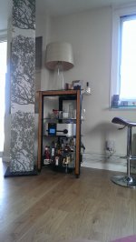
I have owned a pair of 1+1s with the subwoofer interface (MK-131-B) for over 25years. I bought them second hand from someone in NJ when I lived in Vancouver, BC. I now live in NJ with them. The only maintenance I have done over the years is re-coned the subwoofer speaker (in Vancouver) and replaced the grill covers to increase the WAF (wife approval factor).
They continue to sound amazing.
Is there anything I should consider replacing (capacitors etc) as a preventative maintenance initiative?
Attachments
It's really something special when you have found your ultimate sound without all the Hype to dissuade you along the way over the years.
At the very least your not the typical insecure audiophile that needs someone else to tell them what sound good
Love the style of fabric and blending of the background
Right on and enjoy for many years to come!
Regards
David
At the very least your not the typical insecure audiophile that needs someone else to tell them what sound good
Love the style of fabric and blending of the background
Right on and enjoy for many years to come!
Regards
David
I have owned a pair of 1+1s with the subwoofer interface (MK-131-B) for over 25years. I bought them second hand from someone in NJ when I lived in Vancouver, BC. I now live in NJ with them. The only maintenance I have done over the years is re-coned the subwoofer speaker (in Vancouver) and replaced the grill covers to increase the WAF (wife approval factor).
They continue to sound amazing.
Is there anything I should consider replacing (capacitors etc) as a preventative maintenance initiative?
Hey, that's some snazzy grille cloth! What sort of fabric is it?
As preventative maintenance, I wouldn't bother to replace anything, as any failures down the road will likely be benign and cause no harm to other components. At some point in the life of some Acoustat speakers, the output of the bias system may fade, which would indicate replacement of the five ceramic disc capacitors in the bias multiplier, and less commonly, the five high-voltage diodes in the multiplier.
Any other failures tend to be quite random, and hardly worth discussing. That is, cross that bridge when you come to it.
As far as upgrades are concerned, some sonic improvement may be noticed by replacing the electrolytic in the input network with a film-type capacitor. I don't recall the exact value in the MK-131, probably around 220-uF, which means a film-type replacement will be quite large.
Or, one could perform the C-Mod to the interface, which has its own advantages, along with using a smaller value capacitor that is more practical to replace with a film type. I'm not sure if the C-mod was ever officially applied to the MK-131, but I see no reason that it wouldn't have the same advantage.
I'm attaching the C-Mod instructions in case you are interested. The instructions are written for the full-range MK-121 interface, so some interpretation will be required. However, the changes to the input network should be the same.
P.S. The distributor part numbers referenced in the instructions may no longer be valid.
Attachments
Last edited:
Acoustat 1+1s Grille fabric
The fabric is from a Finnish Design house called "Marimekko". It is a very thin fire-proof fabric (sonically invisible).
My wife is Finnish, hence the increased WAF (Wife Approval Factor). Brilliant thinking on my part, I thought.
Thanks for all the info. This forum is great.
The fabric is from a Finnish Design house called "Marimekko". It is a very thin fire-proof fabric (sonically invisible).
My wife is Finnish, hence the increased WAF (Wife Approval Factor). Brilliant thinking on my part, I thought.
Thanks for all the info. This forum is great.
Absolutely! Is there a U.S. source for the fabric?Brilliant thinking on my part, I thought.
Andy
I have always wondered why in the Spectra series of speakers that the first segment to receive the signal is, as an example, on right speaker, the right hand side of first (Innermost) panel?
So on my Spectra 33 right hand side, the standard configuration is:
Panel 1 , Segment 1 2 , segment 2 first
Panel 2 , Segment 3 4
Panel 3 , Segment 5 6
Did you ever try another configuration say the left most segment on the right side?
Panel 1 , Segment 1 2 , segment 1 first?
Panel 2 , Segment 3 4
Panel 3 , Segment 5 6
Or
Panel 1 , Segment 1 2
Panel 2 , Segment 3 4 , segment 3 first?
Panel 3 , Segment 5 6
Thanks
Andrew
I well give my input on my Spectra 11s an 3s......an some pic for others ...these pic are the stock Spectra panel setups....
I have tried every way that you have posted..an more...an now I run Spectra panels with all parts of the panel setup on fullrang taps only for the best sound.........well for me...
The Spectra transfourmers sound better than the older 121 non-Spectra. type....it my be that the Spectra trans can be ran fullrang an....don't need a C-type crossover .....
Attachments
-
![456963d1420256495-acoustat-answer-man-here-spectra_sectors[1].jpg](/community/data/attachments/452/452088-ed9a5c3f22aaa64b9de5858e3244bb72.jpg) 456963d1420256495-acoustat-answer-man-here-spectra_sectors[1].jpg69.9 KB · Views: 386
456963d1420256495-acoustat-answer-man-here-spectra_sectors[1].jpg69.9 KB · Views: 386 -
![456961d1420256495-acoustat-answer-man-here-spectra_11_sector_sizes[1].png](/community/data/attachments/452/452098-c247e118ea25fd00b4de4d46a5eeb02b.jpg) 456961d1420256495-acoustat-answer-man-here-spectra_11_sector_sizes[1].png312.6 KB · Views: 364
456961d1420256495-acoustat-answer-man-here-spectra_11_sector_sizes[1].png312.6 KB · Views: 364 -
![456962d1420256495-acoustat-answer-man-here-spectra_22_sector_sizes[1].png](/community/data/attachments/452/452104-b64e3f8a825e86653dda5344183db030.jpg) 456962d1420256495-acoustat-answer-man-here-spectra_22_sector_sizes[1].png222.9 KB · Views: 371
456962d1420256495-acoustat-answer-man-here-spectra_22_sector_sizes[1].png222.9 KB · Views: 371 -
![457563d1420493129-acoustat-answer-man-here-spectra_stator_wires[1].png](/community/data/attachments/452/452111-ae3d5085b5d131dd19ec788c155ffab2.jpg) 457563d1420493129-acoustat-answer-man-here-spectra_stator_wires[1].png54 KB · Views: 354
457563d1420493129-acoustat-answer-man-here-spectra_stator_wires[1].png54 KB · Views: 354
I was working with a guy that has Spectra 11-1100.....Looking At the old 100mf cap. crossover...An trying to help him understand why using 5-6 poly caps to make up the 100mf.... would give better sound.....when he said that in most ways he like the sound of the 11 better than his Spectra 33....that only have a one ohm res in the input....when there ran fullrange
So as we sat looking at the schematic......I saw agine see pic 1 ...that these Spectra 11-1100 were the only Acoustats panel interfaces..... that ran any part of the panel off the tranfourmer winding it self......with out a res. or cap before the panels.....
With the older Acoustat 121 interfaces....my setup is 3ea 9" panels flat per side
So I took the outside one panel an Moved its panel feeds..right off the Secondary..in front of the caps on the mixer board....see pic 2...
The C-mod crossover is there feeding the high freakquence transfourmer primary.....so the one outside panel well only play what ever the C-mod is......like maybe above 1khz...
Wow.......with the other 2 panels in the stock setup.....vary nice ..more output..Better topend....gives just a little of the Spectra type dispersion......It been about two weeks...an I like it a lot.....vary good sounding Mod...NO down side I see.... less is more.....the best sounding cap...is NO cap!
So I thought I would pass it a long.......befor the cell phone kills these sites...
All just onemansfinding.....all just one more way to get better sound out of the old Acoustats..............
Attachments
![453423d1418321176-acoustat-answer-man-here-spectra_11_schematic[1].gif](/community/data/attachments/444/444057-7d0e0d8c86b3060c46547c35f1a91689.jpg)
![362325d1374834931-acoustat-2-2-c-mod-repair-mk-121c_xovr-5b1-5d-1-[1].gif](/community/data/attachments/444/444062-835ef1b9282f67e5ab2c15b797326720.jpg)
- Home
- Loudspeakers
- Planars & Exotics
- Acoustat Answer Man is here