The 1ohm with the Ziptye is a newone on me....I had over 10pr of 121 an never seen that....................but not the prob..with noise ..I would not think
I would take Zips off.. that one ohm can get hot......but that me....
Sounds like your amp is seeing a dead short.......like a dead transfourmer!
less you can see a wire tuching the case.....other can say...
good luck
I would take Zips off.. that one ohm can get hot......but that me....
Sounds like your amp is seeing a dead short.......like a dead transfourmer!
less you can see a wire tuching the case.....other can say...
good luck
Attachments
![470737d1425955997-acoustat-answer-man-here-image[1].jpg](/community/data/attachments/444/444193-71ac0a5eea554100e15c5ec66b24662e.jpg)
Have you checked all fuses? Start there.
I agree on the zip-tie - never seen it either. Has the unit undergone any goofy mods?
With unit disconnected from speakers measure the bias voltage (DC) with ground probe on chassis ground and red probe on bias pinout - you should read around 70 - 75vdc (should equate to 5kv with probe loading) - be careful, as main voltage exists.
Then unplug, wait a few minutes, and measure the speaker outs resistance - should be low, but not shorted - mine are around or just under 1 ohm, I think.
John.....Look Cherry......121a not C mod but newer tranfourmers....by the way I went back to the 121a.....Wow....it tuff... with the C mod the sound is smother an maybe ezer to drive...not sure....but 121a... the sound is vary raw......you are there...boy 121a sound takes me back.... to the sound of the tube sevos amps in my frist AcoustatXs
Hi, I recently picked up a pair of Acoustat Servo amps to power Monitor X speakers. I've read that the gain stage is a weakness of the amp. I'm curious whether it would be possible to successfully bypass the initial opamp gain stage (which also provides some equalization) and run a preamp (potentially a Bottlehead Beepre that I'm planning to build) directly to the power amp stage. Any help/suggestions here would be greatly appreciated. Thank you.
I must not be doing this right. I turned the voltmeter to DCV, and touched the black lead to the box, red to where the bias pin would go, got a spark where the black lead touches the box, but the meter barely moved. The same result with the working interface. The speaker out resistance didn't make the ohm reading move at all. How can I test to see if the transformers have failed?
I'm trained in medicine, so electronics are completely new to me, appreciate all the help.
I'm trained in medicine, so electronics are completely new to me, appreciate all the help.
I must not be doing this right. I turned the voltmeter to DCV, and touched the black lead to the box, red to where the bias pin would go, got a spark where the black lead touches the box, but the meter barely moved.
Due to the level of high voltage present when powered up the meter needs to be connected to the HV tap and chassis ground while the box is powered OFF and after it has been allowed to discharge. The problem is that approximately 5kv will be on the tap you measured when no meter is connected. When you connect the leads to the tap the 10 meg ohm meter resistance forms a pathway to chassis ground. Then when you power the interface box ON the connected meter will create a voltage divided circuit pathway to ground that keeps the measured voltage from rising above a much lower [and safer for your meter] level of 60 - 80vdc. Unfortunately you may have damaged your meter when you "sparked" it to the live 5kv tap. Most meters will not handle anything above 1kv.
If your meter is dead, you can purchase some el-cheapo DMM's for typically < $10 that will work fine for this measurement.
From your description "...meter barely moved..." I get the impression that you used an analog meter.I must not be doing this right. I turned the voltmeter to DCV, and touched the black lead to the box, red to where the bias pin would go, got a spark where the black lead touches the box, but the meter barely moved. The same result with the working interface.
For the test to work, you need a DVM (Digital Volt Meter) that has a 10 Meg ohm input resistance.
It doesn't need to be expensive...something like this would work great:
Amazon.com: INNOVA 3300 Hands-free Digital Multimeter (10 MegOhm): Automotive
Your local Sears or auto supply store would likely have something similar.
The DVM would also have the ability to compare resistance of the transformer windings to determine if they are internally shorted.
I got a SPW-1 that is need of repair, I know I had model info for a replacement 6 inch woofer and cannot find it for the life of me anyone know off the top of the old noggin what the replacements for those are?
Jason
Perhaps someone has identified a woofer that is a suitable replacement, but the original woofers were custom designed for the SPW-1. Anything 'off-the-shelf' will at best be a close approximation, and it would probably be best to replace all four so that you have a matched set.
From your description "...meter barely moved..." I get the impression that you used an analog meter.
For the test to work, you need a DVM (Digital Volt Meter) that has a 10 Meg ohm input resistance.
It doesn't need to be expensive...something like this would work great:
Amazon.com: INNOVA 3300 Hands-free Digital Multimeter (10 MegOhm): Automotive
Your local Sears or auto supply store would likely have something similar.
The DVM would also have the ability to compare resistance of the transformer windings to determine if they are internally shorted.
These discussions of checking the bias voltage are all well and good, but my opinion is that they are akin to checking your car's tire pressure when the engine won't start. I cannot imagine a mechanism whereby a problem in the bias supply could create a loud sound. Indeed, the fact that the speaker produces a loud sound would indicate that the bias is working just fine!
The taps are set in the same position for both interfaces
The amp is a Cinepro 1k2se
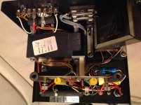
I have examined all of your photos in detail, and cannot discern anything out of place. This is not to say that there isn't...I just can't see anything. I suggest you carefully examine around the two terminal strips to see if a solder-drip may be making contact with the chassis, a sharp point is poking through the wrapper on a capacitor, etc. The defect could be very subtle!
It might be instructive to measure the DC resistance at the input. That is, measure across the red and black input binding posts. This resistance will be quite low, on the order of 1 ohm or less, so you'll need a better-quality meter capable of resolving low resistances.
Regarding the plastic tie wrap and holder on that 1-ohm resistor. That was an ill-advised method used by the factory for a short time. The preferred method is to use short pieces of stiff solid wire to attach the resistor to the terminal strip so that the resistor hangs in mid-air for proper cooling. It can get hot in operation. However, this is not the cause of your problem.
Another item you might want to address is the green corrosion on the high frequency balance control resistor. This can usually be cleaned off with fine emery paper, and be sure to clean under the sliding contact as well. Again, I seriously doubt this is causing your problem: just something to address once you have the problem solved.
... I cannot imagine a mechanism whereby a problem in the bias supply could create a loud sound. Indeed, the fact that the speaker produces a loud sound would indicate that the bias is working just fine!
Agreed. I was just pointing out why the bias checking procedure likely didn't work as expected.
Also, that the DVM would be useful to use for resolving small differences in transformer winding resistance that might point to the problem.
It is unclear to me whether the loud sound happens:
1) when speakers are plugged in, even without an amplifier hooked up
2) only with amplifier hooked up, whether or not music is playing
3) only when amplifier is playing music
Actually, know that I think about it, there is one possibility that will cause noise in case 1) that is related to the bias supply. If a poor connection(or very small gap) develops somewhere along the bias chain to the diaphragm, you can get a small continuous arc across the gap that allows the diaphragm to charge up but continuously generates a noise. This may happen at the solder joints for the HV bias resistor or connector. You can experience this by pulling the bias wire from its socket and holding it very close to it(but not touching...usually 1mm - 2mm away) until the small arc appears.
I suppose that's a possibility, so the integrity of the red socket's connection to the board should be checked. A similar poor connection before the 500-megohm resistor probably would not cause such a sound due to the long time-constant of the circuit. But definitely worth looking into!
I would love to know the answers to your list of questions, as my own similar questions have gone unanswered, as well as my request for a description of the 'loud sound', so as to help diagnose this bizarre problem.
I would love to know the answers to your list of questions, as my own similar questions have gone unanswered, as well as my request for a description of the 'loud sound', so as to help diagnose this bizarre problem.
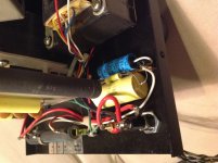
Sorry Any, didn't mean to be vague about the sound. it was hard to describe. perhaps a lower freq version of a loud trumpet. but I do have an update...the gentleman, Verne, that sold me the speakers dropped by and tried to help troubleshoot. he didn't see anything with the interface. I hooked it up to the amp, plugged it into the power strip, nothing. Then I turned the amp power on, and the sound came on, and he saw a blue high voltage arc. we located the arc to the yellow and blue wires, coming out of the biggest transformer. There appeared bare, exposed wire where the arc was coming from the two wires, the conductive coating seemed to have been burnt. Verne thought there may be something else wrong that caused the two wires to arc. Does anyone know if there was a reason why this arc came about? or was it just simply a fault in the conductive coating. i was thinking of wrapping 10 layers of electrical tape around the bare spots.
Sorry Any, didn't mean to be vague about the sound. it was hard to describe. perhaps a lower freq version of a loud trumpet. but I do have an update...the gentleman, Verne, that sold me the speakers dropped by and tried to help troubleshoot. he didn't see anything with the interface. I hooked it up to the amp, plugged it into the power strip, nothing. Then I turned the amp power on, and the sound came on, and he saw a blue high voltage arc. we located the arc to the yellow and blue wires, coming out of the biggest transformer. There appeared bare, exposed wire where the arc was coming from the two wires, the conductive coating seemed to have been burnt. Verne thought there may be something else wrong that caused the two wires to arc. Does anyone know if there was a reason why this arc came about? or was it just simply a fault in the conductive coating. i was thinking of wrapping 10 layers of electrical tape around the bare spots.
Now we are getting somewhere. The arcing between blue and yellow wires is not an unheard-of problem on the MK121 low frequency transformer. It is usually caused by a failure of the insulation, sometimes aggravated by overdriving the speaker. I reexamined the photos supplied, and could not see any evidence of the burnt insulation, so perhaps the photos were of the 'good' interface?
In any case, electrical tape is not a great solution. I recommend a two-prong approach. First, get some flexible PVC tubing from an electronic distributor, with an internal diameter suitable to slip over the blue and yellow wires. Disconnect the wires from the printed circuit board and slip the tubing over the wires, covering as much of the wire length as possible. Reconnect the wires to the board. Later factory-built interfaces used this method to decrease the chance of arc-over between these wires, so it's probably a good idea to apply this change to both interfaces.
Second, use epoxy to coat the area where the wires exit the transformer. It is okay if some of the epoxy drips down inside the transformer (it may even help the situation). Several applications may be necessary to build up a sufficient thickness.
Finally, there is no guarantee that you can fix the problem. If the arcing is occurring down inside the transformer, you may not be able to sufficiently insulate the area, especially if a carbon path has been established. At that point, replacing the low frequency transformer will be necessary.
- Home
- Loudspeakers
- Planars & Exotics
- Acoustat Answer Man is here