1st order lowpass filter is an inductor, not a cap.
Whoops, yes, the series caps I identified were for high pass at those frequencies. The 50hz low pass series inductor value for 4ohm sub at first order is 12.7mH, and at 250hz is 2.5mH. Thanks for correction...
-3db point (for example) on the system response curve is very different between 2, 4 or 6 panel system.
The only way of achieving the the same LF SPL response using fever panels is by pushing more power into them.
More power = longer excursion.
Yes again, understood, but the switch on the MK-2123 is either drives the panel(s) full range, or just high-pass over 100hz. Anything you do on that internal crossover point on the sub-out binding post (in this example, add series capacitance to lower to 50hz) should not make further demands on the panel(s) that it cannot already do, correct? He is not adding or removing panels, which would change the -3db point.
But I see your point - driving the panel full range may get 90db SPL at a certain power level, and that same power would drive same panel 92db SPL when you remove all frequencies under 100hz...I can see this...
Last edited:
Hello Andy!Hello Audio Enthusiasts! Some of you may know my work on www.audiocircuit.com, where for many years I have been helping to advise Acoustat owners. I was an engineer and manager with Acoustat, starting when the David Hafler Co bought Acoustat out of bankruptcy, right up to the very end of US production under Rockford Corp ownership (sad day that was!). So I thought I'd lend a hand here, too, because I LOVE Acoustats and want to help as many owners as possible to keep their Acoustats running for many years to come. I don't sell parts or do repairs, but my advice is FREE! So let me know how I can help YOU with your ACOUSTAT's! (And this being a DYI crowd, I don't mind discussing modifications to the speakers.)
Andy Szabo
I've got a pair of Acoustat Monitor 4s that I'm needing to restore. I posted a thread about it over on Audio Asylum. I'll email you a link so you can see the photos I've posted and will send you my cell number. I'd love to chat with you about bringing these up to speed. The guys at Audio Asylum gave me some great tips and advice. Unfortunately, I left off with the restoration but am getting back to it now and would love to discuss some aspects of the restore with you over the phone and the rest I can post here if you're ok with that...
Best regards,
Luther
OOPS
Ok guys i need a bit of help. I rebuilt the crossovers for the 2200's this past weekend and set the bias on method 2 to a perfect 75 on both. I got them back together and one is working but the other is kaput. is there a common screw up i should look for? The bias is working fine, the power light lights (although slightly dimmer than the other) and there is nothing obviously wrong. Can you swap the black leads from the transformer to the crossover and cause this?
Jason
Ok never mind, didn't tighten the speaker terms down. I do have a quick question for andy though. On the passive subwoofer what kind of signal sum circuit did it have?
Glad you got your problem solved. On to your question: the Acoustat SPW-1 does not have a summing network. It contains a total of four woofers within one cabinet, with two woofers assigned to each channel. Therefore, there is no need to use a summing network.
In any case, making a passive left-right summing network at speaker level would be problematic. Passive subwoofers that sum the channels usually do so in the magnetic domain. That is, they use a woofer with a dual voice coil, one for each channel.
Ah, the reason they used 4 woofers makes more sense now. Do you happen to know the effective impedance and sensitivity of the spw system? That would make designing a passive woofer set alot easier. I can understand the use of a single unit for WAF but in my case I can make a set of passives and set them up for better stereo imagining.
Thanks in addvance
Jason
Thanks in addvance
Jason
Ah, the reason they used 4 woofers makes more sense now. Do you happen to know the effective impedance and sensitivity of the spw system? That would make designing a passive woofer set alot easier. I can understand the use of a single unit for WAF but in my case I can make a set of passives and set them up for better stereo imagining.
Thanks in addvance
Jason
I don't know either of those specifications, and if they ever were published, I'm not sure how much they would help you. The impedance of your home-built woofer will depend on its crossover design and woofer selection. The woofer output on the Spectra interface is full range so that it can be used with the system of your choice.
Efficiency of the woofer system will necessarily need to be fairly low in order to match the low efficiency of the ESL. Be prepared to include some attenuation in your woofer's crossover. Or better yet, use a powered subwoofer with active crossover for optimum matching of amplitude, phase, and crossover slope and frequency.
Where to order replacement rocker swtich for a TNT-200?
Hello and Help:
Does anyone know where I can order/purchase a replacement power on/off rocker swith for an Acoustat TNT 200 power amp? The reading on the switch is 'UND LAB INC LIST 20A 125-250VAC 1/HP 125-250WAC MEXICO'. Thanks.
Sincerely,
Kingsley.
Hello and Help:
Does anyone know where I can order/purchase a replacement power on/off rocker swith for an Acoustat TNT 200 power amp? The reading on the switch is 'UND LAB INC LIST 20A 125-250VAC 1/HP 125-250WAC MEXICO'. Thanks.
Sincerely,
Kingsley.
Hello and Help:
Does anyone know where I can order/purchase a replacement power on/off rocker swith for an Acoustat TNT 200 power amp? The reading on the switch is 'UND LAB INC LIST 20A 125-250VAC 1/HP 125-250WAC MEXICO'. Thanks.
Sincerely,
Kingsley.
If memory serves correctly (and it may not) the original switch was made by Carling Switch. Your best bet is to remove the old switch and measure the mounting hole. Such things are fairly standard, so it's just a matter of finding a similar replacement with the same electrical rating and physical mounting. You can probably find something suitable at electronic distributors Digikey, Mouser, Newark or Allied.
Help with Acoustat 1+1 speakers.
I would appreciate any help. I recently bought a set of these with the blue medallion interfaces from CL. the owner mentioned the original owner of these was Mike Scott, the first CEO of Apple computers. In any case, he said they worked fine when he last used them. when I arrived to pick them up, they were disconnected. after getting these home, i plugged them in and got a loud sound from one speaker. the other was fine. switching the interfaces isolated the problem to one interface. the panels are fine. My questions are: has anyone here assembled a list of electronic components to rebuild the interface if the transformers are okay? how to check if transformers are okay? can an electronics neophyte with a solder iron hope to repair this, or do i have to send it to Roy Esposito? Thank you
I would appreciate any help. I recently bought a set of these with the blue medallion interfaces from CL. the owner mentioned the original owner of these was Mike Scott, the first CEO of Apple computers. In any case, he said they worked fine when he last used them. when I arrived to pick them up, they were disconnected. after getting these home, i plugged them in and got a loud sound from one speaker. the other was fine. switching the interfaces isolated the problem to one interface. the panels are fine. My questions are: has anyone here assembled a list of electronic components to rebuild the interface if the transformers are okay? how to check if transformers are okay? can an electronics neophyte with a solder iron hope to repair this, or do i have to send it to Roy Esposito? Thank you
A 'loud sound' coming from the interface is a very unusual symptom. There really isn't anything that I can think of that would produce such a problem. Can you perhaps describe the nature of this sound? Was it a humming sound, a screeching sound, what?
Another question - was it the same amplifier channel that produced the loud sound? I'm wondering if your amplifier channel might have a marginal stability problem when connected to the interface, that caused it to oscillate. Or does the sound occur with no amplifier connected?
Another question - was it the same amplifier channel that produced the loud sound? I'm wondering if your amplifier channel might have a marginal stability problem when connected to the interface, that caused it to oscillate. Or does the sound occur with no amplifier connected?
Last edited:
I should clarify that the sound came from the panels. Upon switching the interfaces from one panel to the other, the affected interface which caused due out sound to be produced from both panels. But the panel sounded fine with the normal functioning interface.
Yes, I had assumed that the 'loud sound' was coming from the panels. But please do describe the nature of the sound, and whether the same amplifier channel was connected to the 'bad' interface when tested on both panels. Does the 'bad interface' play music along with the loud sound, or just the loud sound? I'll need a little more help if I have any hope of helping you with this very unusual symptom. I've been working with Acoustat speakers for nearly 30 years and have yet to hear of an interface doing this.
i talked to the owner, and he wonders if the sound is from a 60 sec hum. Is this plausible from an acoustic interface?
A 60 cycle hum is an extremely unlikely fault mode from an Acoustat interface unless someone has done some crazy modifications to it, or perhaps a wire has become disconnected and is touching something it shouldn't. This is why I was attempting to get you to describe the nature of the sound, whether it was a 60-cycle hum or a higher pitched sound.
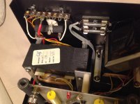
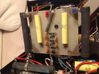
Take a look at the low frequency transformer tap in each interface. This is a multiple-position terminal strip with a user-adjustable position of a push-on spade terminal. For the 1+1, it should be set to the terminal with the small red wire. Having this tap set incorrectly will NOT cause any problems, but I am wondering if the tap may be set differently in the two interfaces. The position of the tap does change the impedance, and it's possible your amplifier is stable in one position and not the other. What amplifier are you using?
Also, try setting the two interfaces next to each other on a table, and compare the two for any differences in wiring, component position, etc.
Update: TNT-200 Power switch replacement found and ordered from Digi-Key.
Hi All:
Just an update. I managed to find a replacement power switch for my Acoustat TNT-200, it was part number RVW41D1100-ND. This is for those who may need to replace the switch on their units. Thanks.
Sincerely,
Kingsley.
Hi All:
Just an update. I managed to find a replacement power switch for my Acoustat TNT-200, it was part number RVW41D1100-ND. This is for those who may need to replace the switch on their units. Thanks.
Sincerely,
Kingsley.
It's hard to describe the sound. Not like a fire alarm, but loud. I could not find anything different between the two boxes. No loose wires. Here are some high res pics from my iPad. Thank you all for helping. Looks like I can only upload a picture at a time.
Attachments
- Home
- Loudspeakers
- Planars & Exotics
- Acoustat Answer Man is here