Built another pair of board to replace the one I wasn't able to troubleshoot. I replaced Q11 because I had extras (10 cost less than 4 at the time) and everything else I could measure was as expected (for me that's just resistors, and think the diodes were working as expected)
Before I apply power to it...
With a 20V transformer, my memory from the previous attempt says I was getting +28.25V / -28.35V (56.7V between +/- solder pads) being read on an F4 board. I haven't checked the wall voltage in a few weeks. After a transformer went out in my yard last year I'm no longer at a constant 125V, but a variable 120.2-122.9 It's hooked up, a bulb tester ready, but I'm going to call it an evening, eat, drink, etc... if there is an obvious mistake, feel free to ridicule to prevent wasted parts!
... if there is an obvious mistake, feel free to ridicule to prevent wasted parts!
It's obvious to me that you need to buy variac before you fire that thing up!
The F4 has 3 pairs of output mosfets...
I also built the F4 clone using the information contained in the published "Operation and Service Manual". In mine the output stage, which operates in push-pull, has two triplets of N and P channel MOSFETs. MOSFETs of the same type are connected in parallel to increase the amount of current they can handle. The devices in each triplet are matched so they will handle roughly the same amount of current.
I don't mean to interrupt from the intelligent comments made by grimberg, wdecho, and everyone else who isn't struggling.
25.38 as measured from solder pads on the old, working F4 board, and wall voltage is at 119.8... new neighbor must be growing something.
I'm putting away toys because so far I'm just drinking, not eating.
How big of a variac for this hobby?
This seems to be very low cost, so I question quality. 5A Variac
Or this:
500VA 0-130VAC Variable Power Transformer | MPJA.COM
Better Yet:
http://www.ebay.com/itm/Variac10A-A...356358?hash=item41aaad4506:g:g4oAAOSw1KxXNTrv
500VA 0-130VAC Variable Power Transformer | MPJA.COM
Better Yet:
http://www.ebay.com/itm/Variac10A-A...356358?hash=item41aaad4506:g:g4oAAOSw1KxXNTrv
Last edited:
I want to convert my stereo F4 from single RCA input to balanced mono using an input transformer as a phase splitter. I have a number of Edcor WSM 10k:10K transformer, so I would like to use them if possible. These transformers have a CT on both the input and output.
Which drawing is the right way to hook this up A or B
Thanks for the help
Debra

Which drawing is the right way to hook this up A or B
Thanks for the help
Debra

Your comment about gain has just got me thinking, in the same way you can use step up transformers for mc cartridges could a similar arrangement be used to step up line level by a factor of say 10 or 20? I appreciate matching impedances and probably having to add some extra caps on the output side would be a hassle but is it workable or just likely to not practical. Im guessing such a step up tx is likely to have a low input impedance and a high output impedance , neither of which is particularly helpful.
![IMG_1815[1].jpg](https://www.diyaudio.com/community/data/attachments/555/555033-11fdd8cda6946aa8e3730be923a055ad.jpg "IMG_1815[1].jpg")

")
Hope I'm not running afoul of some forum rule, but I'm selling some
F4 parts here:
http://www.diyaudio.com/forums/swap-meet/304742-fs-jfets-mosfets-f4-pcb.html
Thanks,
Dennis
F4 parts here:
http://www.diyaudio.com/forums/swap-meet/304742-fs-jfets-mosfets-f4-pcb.html
Thanks,
Dennis
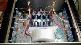
I've been listening to this for about 200 hours. Sounds great as long as I'm not expecting it to recreate a live rock performance.
Using an Aikido 6SN7 preamp, playing FLAC files off a Macbook Pro, no external DAC yet.
http://www.diyaudio.com/forums/attachment.php?attachmentid=606984&stc=1&d=1490203477
About 40 hours of listening ago I put GE 6SL7GT's in V1 and V2, changed resistors as recommended in user manual and increased voltage to ~295 from ~255.
F4 bias is 2.01v average on left channel, 2.0v average on right channel
If I go for the rock album after warming it up (about 120 degrees on heatsinks), the right channel starts degrading in sound before fading in volume. I've measured as high as 145 degrees on the left heatsink. Right heatsink doesn't climb, but doesn't go down in temp either.
This morning tried swapping V1/V2, but haven't swapped V3/V4. Same results after hour plus warm up then listening to loud bass. It happens quite fast, less than two minutes - but I'm expecting it, constantly monitoring temperatures. It climbs to about 125 degrees.
Maybe it is too much gain, will try swapping V3/V4 with known good 6SL7.
Original plans to build two of these and run them bridged - I'll probably scrap because of the difficulty of getting both sides to behave exactly the same.
As visible in the picture I don't have the wiring tidy and exactly symmetrical. It was just fine with the 6SL7's and didn't want to touch a thing. There is no hiss, AC hum, etc. Silent.
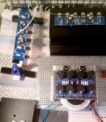
Here are a couple of boards in need of replacement MOSFET's, along with a different way to stuff the transformer / heatsink into a 300mm 4U chassis.
http://www.diyaudio.com/forums/attachment.php?attachmentid=606986&stc=1&d=1490204328
Using an Aikido 6SN7 preamp, playing FLAC files off a Macbook Pro, no external DAC yet.
http://www.diyaudio.com/forums/attachment.php?attachmentid=606984&stc=1&d=1490203477
About 40 hours of listening ago I put GE 6SL7GT's in V1 and V2, changed resistors as recommended in user manual and increased voltage to ~295 from ~255.
F4 bias is 2.01v average on left channel, 2.0v average on right channel
If I go for the rock album after warming it up (about 120 degrees on heatsinks), the right channel starts degrading in sound before fading in volume. I've measured as high as 145 degrees on the left heatsink. Right heatsink doesn't climb, but doesn't go down in temp either.
This morning tried swapping V1/V2, but haven't swapped V3/V4. Same results after hour plus warm up then listening to loud bass. It happens quite fast, less than two minutes - but I'm expecting it, constantly monitoring temperatures. It climbs to about 125 degrees.
Maybe it is too much gain, will try swapping V3/V4 with known good 6SL7.
Original plans to build two of these and run them bridged - I'll probably scrap because of the difficulty of getting both sides to behave exactly the same.
As visible in the picture I don't have the wiring tidy and exactly symmetrical. It was just fine with the 6SL7's and didn't want to touch a thing. There is no hiss, AC hum, etc. Silent.
Here are a couple of boards in need of replacement MOSFET's, along with a different way to stuff the transformer / heatsink into a 300mm 4U chassis.
http://www.diyaudio.com/forums/attachment.php?attachmentid=606986&stc=1&d=1490204328
Attachments
- Home
- Amplifiers
- Pass Labs
- A guide to building the Pass F4 amplifier