Re: Typo
I believe the typo in the F4 article simply the was the designation of the two clamping diodes from the power Mosfet gate resistors to Output. The original schematic had "2N4736," instead of the correct 1N4736. Interestingly, this typo also found its way into the BA-2 article.
The store F4 schematic appears to be based on the earlier May 2007 schematic, as opposed to the June 2007 schematic which was published in the F4 manual. The principal change from the May 2007 schematic and the store schematic is that in four places there is doubling up of the 220 uF capacitors, rather than the single ones in the initial schematic.
Hi Jeffs,
What values are you using for R8, R9 and P1, and what output devices are you using?
Dennis
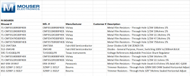
Please, no one use this as a base for a B!11 of Ma+eria1z. There are many changes I would make if ordering over again, much of this was ordered two years ago.
Based on the schematic on first page of this thread.
R1 = 1K RN55D1001FRE6
R3, R4 = 22 ohm RN55D22R1FB14 F4 Service Manual suggests 10K
R5 = 1K RN55D1001FRE6
R6, R7 = 10K RN55D1002FB14
R8, currently installed 22.1K, (RN55D2212FB14) current plan is to switch to 27K
R9, originally used 10K (RN55D1002FB14), tried 4.5K and could only get to 60mV. Put in 5.6K but something in the RFI/EMI power module inlet smoked... I had a bad solder joint on R9 at the time and maybe something else shorted blowing a 3.x amp fuse at the same time. I have a week of timeout as I redo the back panel to accept a common IEC switch / fuse.
Gate resistors are 100 RN60D1000FB14. As you mentioned the F4 service manual calls for 150 R. I'm curious as to why and what the expected result may be.
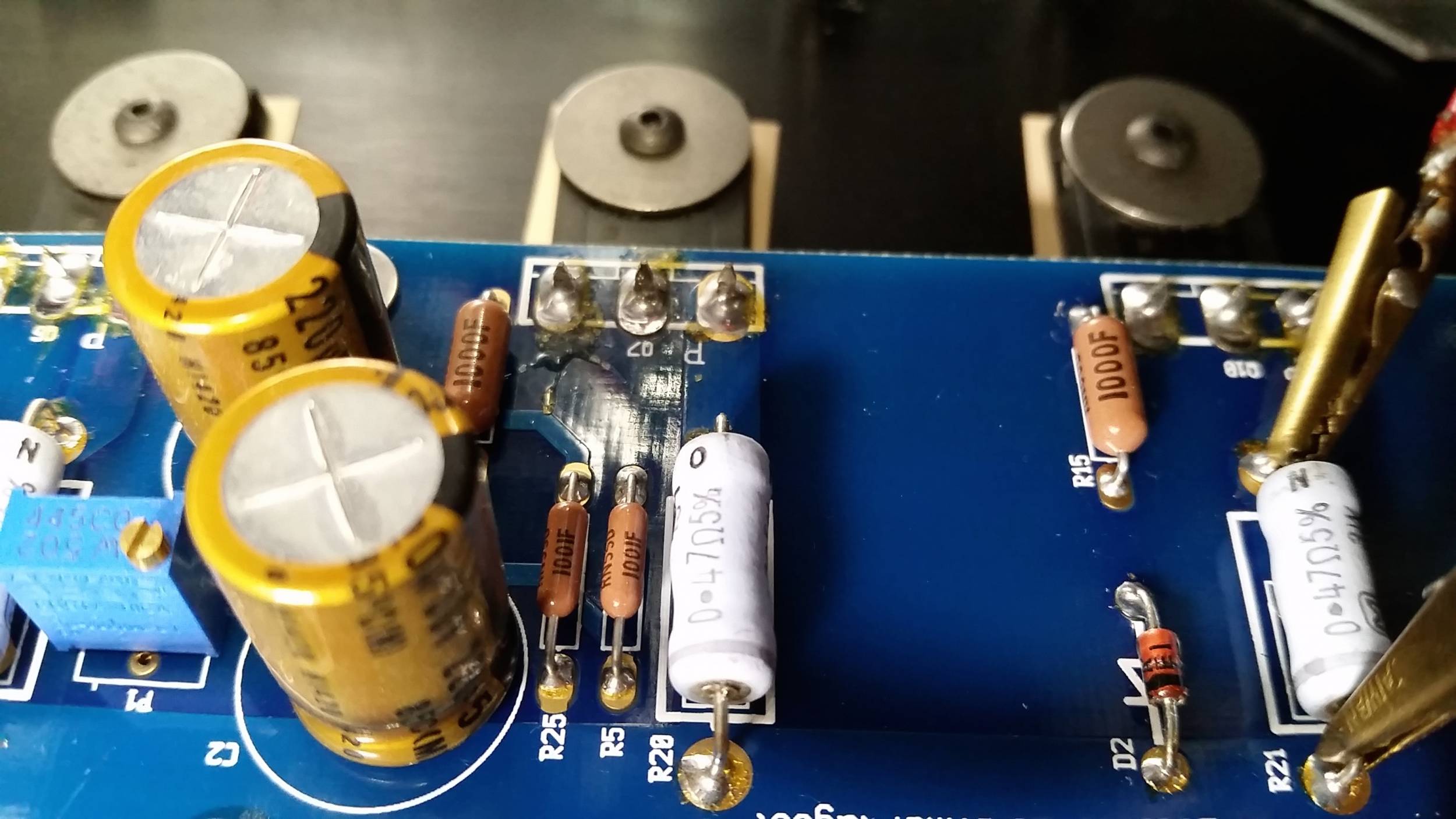
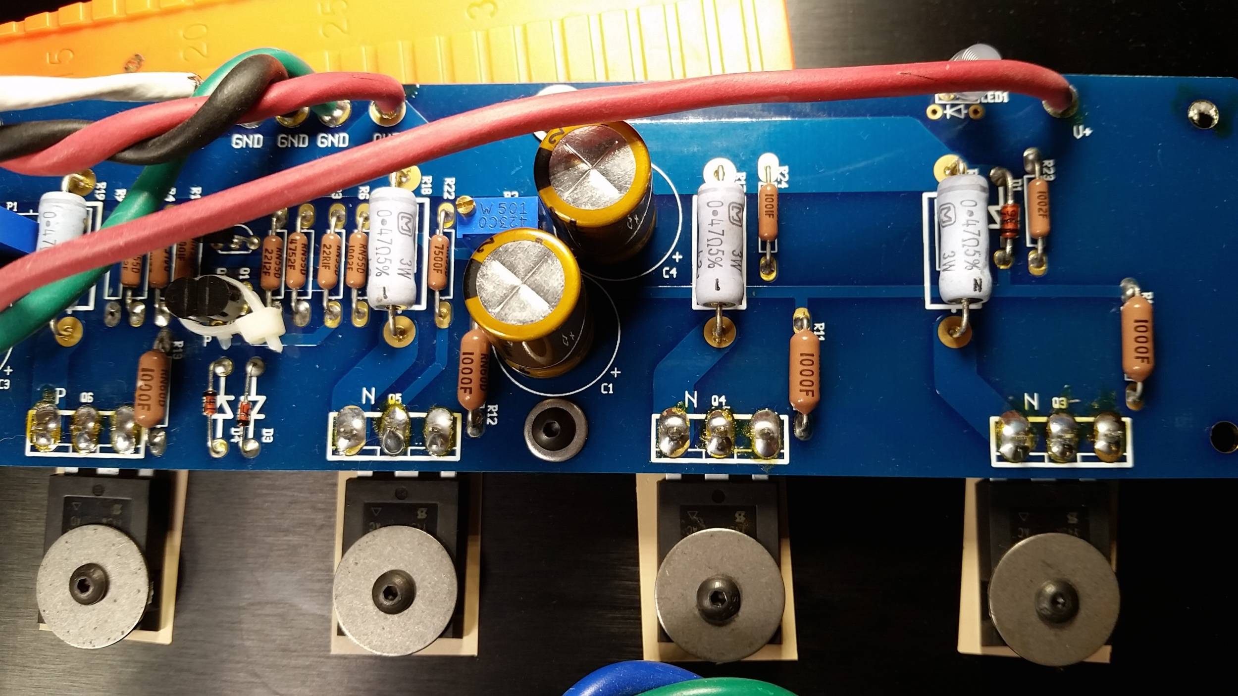
For the Source Resistors, 3W 0.47 R ERX-3FJR47
R22 = 750 RN55D7500FB14
R23 = 10K RN55D1002FB14
R24, R25 = 1K RN55D1001FRE6
Capacitors are 200uf 50V Nichicon "Fine Gold" UFG1H221MHM1TO. I don't know what the result of going with 50V over 35V for sound but if it comes down to removing the boards from the heatsinks I may replace with the hint from Nelson Pass of Elna Silmic II - again 35V or 50V? The 50V would look cooler, I don't know the result on extra voltage on how they sound. It's something I want to know, but should be focused on one thing at a time which I don't do well

P1 = 5K Bourns 25 turn
P2 = 500 "
Q1= 2SK170BL
Q2= 2SJ74BL
The IRFP240 and IRFP9240 as well Q1/2 were purchased from Alex in Israel almost two years ago.
It looks like the store BOM is based on a slightly older schematics dated 4/17/07 (see attached.)
The differences between that and the current 6/4/07 one seem to be
1) lower degeneration resistor at R3, R4 (from 22ohm to 10 ohm)
2) gate resistors went from 100 ohm to 150 ohm
3) R8 from 22.1K to 27.4K.
Cheers,
Dennis
The first question I had when comparing the two schematics was - what is the effect of having 100 vs 150 ohm gate resistors?
I'll probably order 10 ohm options for R3, R4 - they are next to Q1/Q2 in the schematic... as mentioned I used
Q1= 2SK170BL as listed in DIYAudio schematic
Q2= 2SJ74BL as listed in DIYAudio schematic
instead of
Q1= 2SK370 as per F4 Service Manual schematic
Q2= 2SJ108 as per F4 Service Manual
Someone here must have an opinion on the difference and if degeneration resistors R3 / R4 values should be modified.
Yes, it is DIY Audio and I should just try each and try to put my experience in words to share. At the same time, the parts I found matched two years ago may not be available... I'm not very good at rework, if I am removing a solder pad I can only imagine the stress on the more sensitive components.
I haven't started to build the third and fourth F4 board.
I'm ordering 16 gauge silver plated stranded copper with PTFE coating from apexjr because it costs the same as any mystery % copper content wire. I've used a few gallons of gas, days in traffic and a many hours searching for wire in my city and online. This is for the connections between the PSU and F4 boards as well as the output to the speakers. If the silver plated wire in these locations is a problem, let me know.
I'm hoping to keep the shielded twisted pair for the signal input.
I might go with more PSU capacitance since I'm at the minimum of 60K per rail, 35V caps. Again, 400VA 20V toroids.
Gate resistors can safely be anything from 22ohm to about 680 ohm with no effect on operation. They are there to help damp any ultrasonic ringing or oscillations that might be present. A larger value damps this a little better. Use what you have installed, don't change them.
Keep the 22ohm Jfet source resistors. They are not contributing to your issues.
The capacitors you currently have are, 1) really nice audio grade caps, 2) of the proper capacitance and voltage rating for the job, and 3) are in no way contributing to your problems.
Why on earth would you want to change them???
K170/J74 vs. K370/J108 -- These are the exact same transistor guts packaged in slightly different outside plastic. There is some minor differences in terms of power dissipation, but for the purposes of this circuit, can be regarded as identical parts.
No problem at all, as long as you are using silver-bearing solder. If not, the joints will corrode in a few years. I love Teflon, so I like the idea of that wire. Other than that, wire is wire.
It's fine, don't change it.
Hopefully some of your questions have been answered.
Currently I suspect you have a short somewhere in/near the IEC or elsewhere, or just a faulty IEC, as changing the R9 resistor value would not smoke it. Please post photos.
Keep the 22ohm Jfet source resistors. They are not contributing to your issues.
Capacitors are 200uf 50V Nichicon "Fine Gold" UFG1H221MHM1TO. I don't know what the result of going with 50V over 35V for sound but if it comes down to removing the boards from the heatsinks I may replace with the hint from Nelson Pass of Elna Silmic II - again 35V or 50V? The 50V would look cooler, I don't know the result on extra voltage on how they sound. It's something I want to know, but should be focused on one thing at a time which I don't do well
The capacitors you currently have are, 1) really nice audio grade caps, 2) of the proper capacitance and voltage rating for the job, and 3) are in no way contributing to your problems.
Why on earth would you want to change them???
K170/J74 vs. K370/J108 -- These are the exact same transistor guts packaged in slightly different outside plastic. There is some minor differences in terms of power dissipation, but for the purposes of this circuit, can be regarded as identical parts.
I'm ordering 16 gauge silver plated stranded copper with PTFE coating from apexjr because it costs the same as any mystery % copper content wire. ... This is for the connections between the PSU and F4 boards as well as the output to the speakers. If the silver plated wire in these locations is a problem, let me know.
No problem at all, as long as you are using silver-bearing solder. If not, the joints will corrode in a few years. I love Teflon, so I like the idea of that wire. Other than that, wire is wire.
I might go with more PSU capacitance since I'm at the minimum of 60K per rail, 35V caps. Again, 400VA 20V toroids.
It's fine, don't change it.
Hopefully some of your questions have been answered.
Currently I suspect you have a short somewhere in/near the IEC or elsewhere, or just a faulty IEC, as changing the R9 resistor value would not smoke it. Please post photos.
Last edited:
The postal service is running slow, no new wire yet, and forgot to order the XLR input.
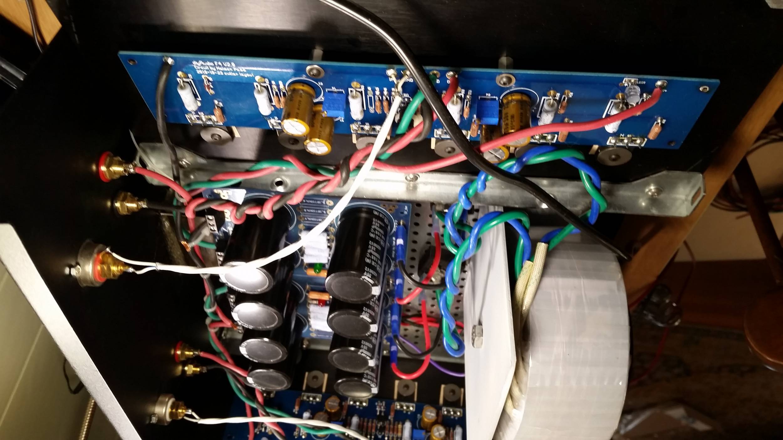
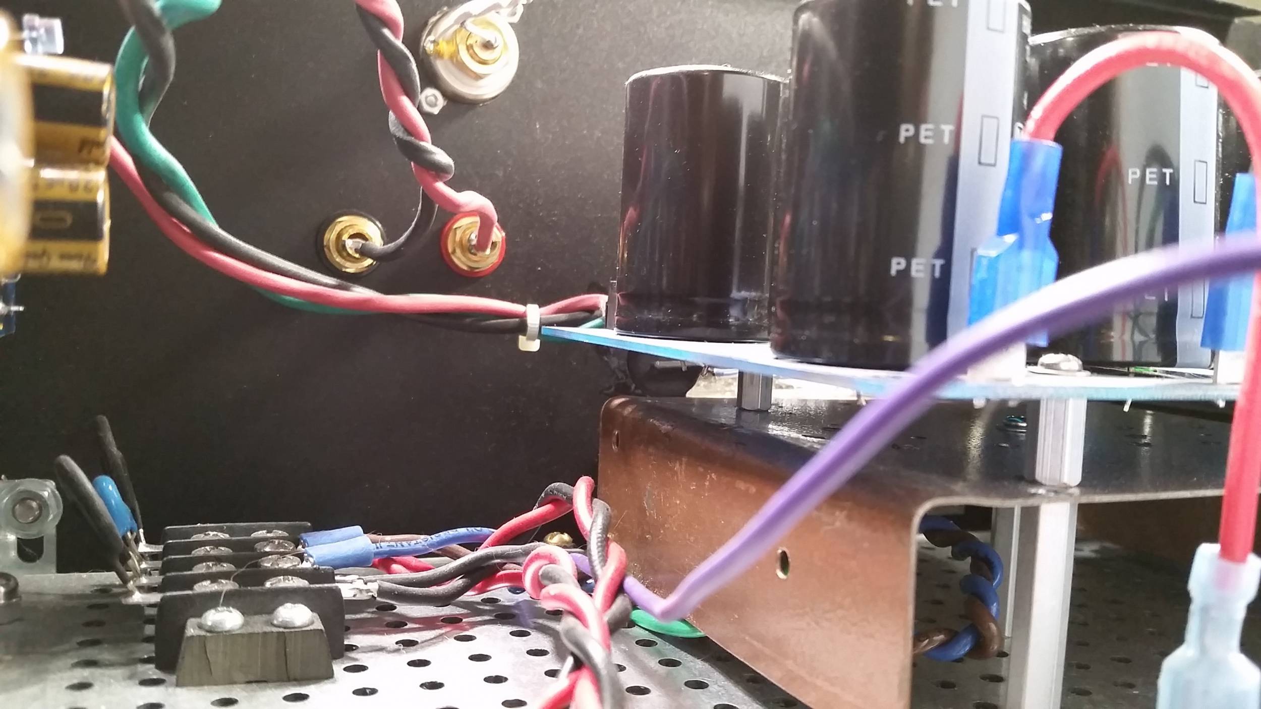
Things are going to get tight in the chassis. The old IEC was horizontal, I mounted it as low as possible and mounted the power supply above it.
Ok, so what's that thing between the power supply PCB and the IEC? A piece of steel which I plated with copper while working on another art project. Instead of spraying clear coat to preserve the finish I used copper spray paint.
Some of these pictures are not showing up so if you want to view them you will have to click on the link. I can see what I did wrong, but don't know how to fix it.

I ordered the same Schurter 4304.6090 IEC inlet as sold with the deluxe chassis rear panel kit for the new back panel. They come with a fuse holder that holds two fuses instead of one. I am guessing two are required, originally designed for 250V, and using US 120V one will be for hot, one for neutral? The warning on the cover of the fuse holder states "use only a 250V fuse". On hand I have 4a 125, and 3.1a 250v, and a hardware store nearby with other options.
If going with the same RCA plus XLR setup as Nelson Pass (I want option to switch between preamps) based on the pictures I've been able to find it appears he runs the wires from the XLR pin + to the RCA + on the other side. XLR pin - goes to the ground on the PCB, so XLR pin ground goes to... (a star ground on the chassis?)
I'm going to have to steal a photo, if this is going to get me into trouble I apologize in advance and a moderator can delete the link, and hopefully not make me have a "time out". I just reviewed the forum rules and didn't see anything but still don't consider it good etiquette.

The way I have it set up currently with two conductor shielded wire currently being used to the RCA. The shielding sheath is attached at the PCB.

That hole ground hole pad on the F4 PCB is going to get quite full. Having a little trouble conceptualizing the right combination for doing the RCA + XLR.
If there is an off the shelf jumper for the XLR when using the RCA inputs give me a hint, or I'll make my own...
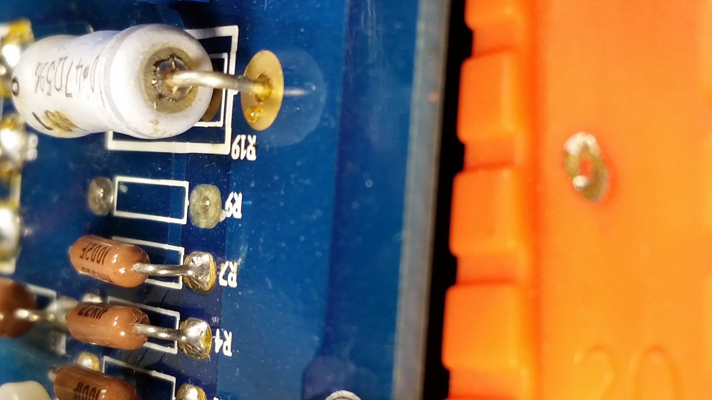
Only because the devil on my shoulder is going to be telling me I should have tried what Nelson Pass is fond of, and that if there was enough rework with resistors to be done I will have to remove the boards from the heatsinks, which is a lot of work. Example is that R9 solder pad came off, and after a week of looking for a solution all I can come up with is to put a strand of copper wire through the hole, coat hole interior, back of pad(s) and copper strand with rosin / flux (all I have on hand is a pen of Kester 951). It is my fault on the pad coming off, believe I was using too wide of a solder wick with too much heat.
[/QUOTE]
Things are going to get tight in the chassis. The old IEC was horizontal, I mounted it as low as possible and mounted the power supply above it.
Ok, so what's that thing between the power supply PCB and the IEC? A piece of steel which I plated with copper while working on another art project. Instead of spraying clear coat to preserve the finish I used copper spray paint.
Some of these pictures are not showing up so if you want to view them you will have to click on the link. I can see what I did wrong, but don't know how to fix it.
I ordered the same Schurter 4304.6090 IEC inlet as sold with the deluxe chassis rear panel kit for the new back panel. They come with a fuse holder that holds two fuses instead of one. I am guessing two are required, originally designed for 250V, and using US 120V one will be for hot, one for neutral? The warning on the cover of the fuse holder states "use only a 250V fuse". On hand I have 4a 125, and 3.1a 250v, and a hardware store nearby with other options.
If going with the same RCA plus XLR setup as Nelson Pass (I want option to switch between preamps) based on the pictures I've been able to find it appears he runs the wires from the XLR pin + to the RCA + on the other side. XLR pin - goes to the ground on the PCB, so XLR pin ground goes to... (a star ground on the chassis?)
I'm going to have to steal a photo, if this is going to get me into trouble I apologize in advance and a moderator can delete the link, and hopefully not make me have a "time out". I just reviewed the forum rules and didn't see anything but still don't consider it good etiquette.
The way I have it set up currently with two conductor shielded wire currently being used to the RCA. The shielding sheath is attached at the PCB.
That hole ground hole pad on the F4 PCB is going to get quite full. Having a little trouble conceptualizing the right combination for doing the RCA + XLR.
If there is an off the shelf jumper for the XLR when using the RCA inputs give me a hint, or I'll make my own...
The capacitors you currently have are, 1) really nice audio grade caps, 2) of the proper capacitance and voltage rating for the job, and 3) are in no way contributing to your problems.
Why on earth would you want to change them???
Only because the devil on my shoulder is going to be telling me I should have tried what Nelson Pass is fond of, and that if there was enough rework with resistors to be done I will have to remove the boards from the heatsinks, which is a lot of work. Example is that R9 solder pad came off, and after a week of looking for a solution all I can come up with is to put a strand of copper wire through the hole, coat hole interior, back of pad(s) and copper strand with rosin / flux (all I have on hand is a pen of Kester 951). It is my fault on the pad coming off, believe I was using too wide of a solder wick with too much heat.
[/QUOTE]
thanks, picked up some Cardas quad eutectic to play with.No problem at all, as long as you are using silver-bearing solder. If not, the joints will corrode in a few years. I love Teflon, so I like the idea of that wire. Other than that, wire is wire.
It's fine, don't change it.
[/QUOTE
You say don't change anything with the exception of finding a good value for R9. I have the following options:
- 4.7K
- 5.6K
- 5.62K
- 6K
- 10K
managed to come up with more questions. doesn't mean people have to answer them.Hopefully some of your questions have been answered.
Currently I suspect you have a short somewhere in/near the IEC or elsewhere, or just a faulty IEC, as changing the R9 resistor value would not smoke it. Please post photos.
If people like photos, here is me considering shrinking the PSU further, possibly not using a PCB at all and the 47000uf caps... or a V2 PSU - top right is an 18 gauge steel template which could support the caps on one of the V2 boards. Probably not going to happen because I don't know what 4 caps with 8 mOhms ESR each will do and don't have any PSU design tools... It is someone's Aleph X PSU plan I was ran across yesterday, but realized it might have been calling for a total of 8x 47000uf caps!!!

This is a taco. More specifically a bean, potato and cheese taco from Taco Deli with Doña and Roja sauce on the side.
Oh, there is the Schurter IEC which fits the panel cutout better than another one I had on hand. Do the notches in the speaker post cutouts have something to do with preventing them from spinning in place? No hole for the XLR, I need to see where the power supply is going to go before I start cutting.

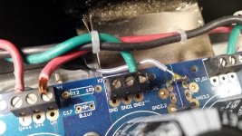
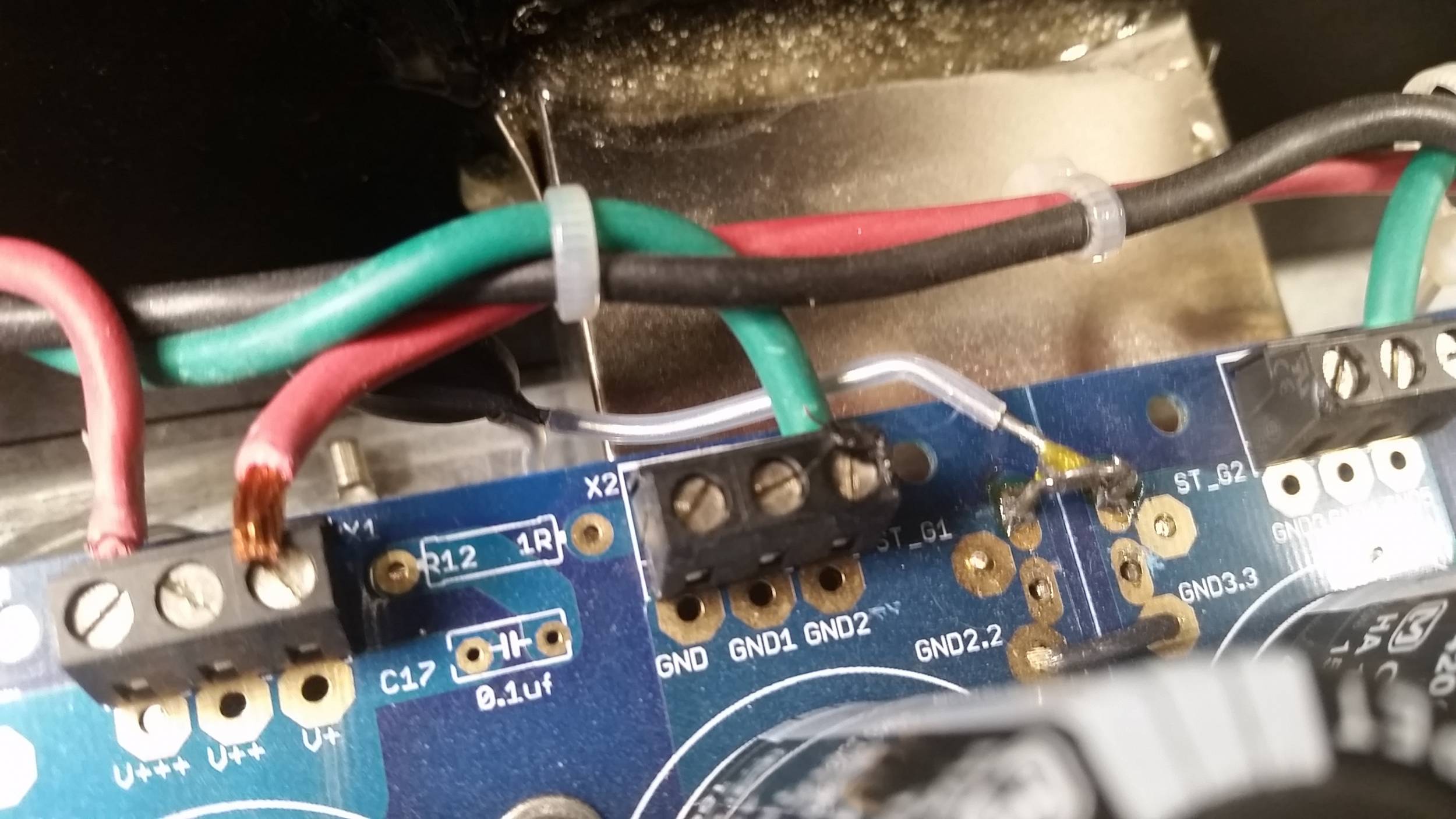
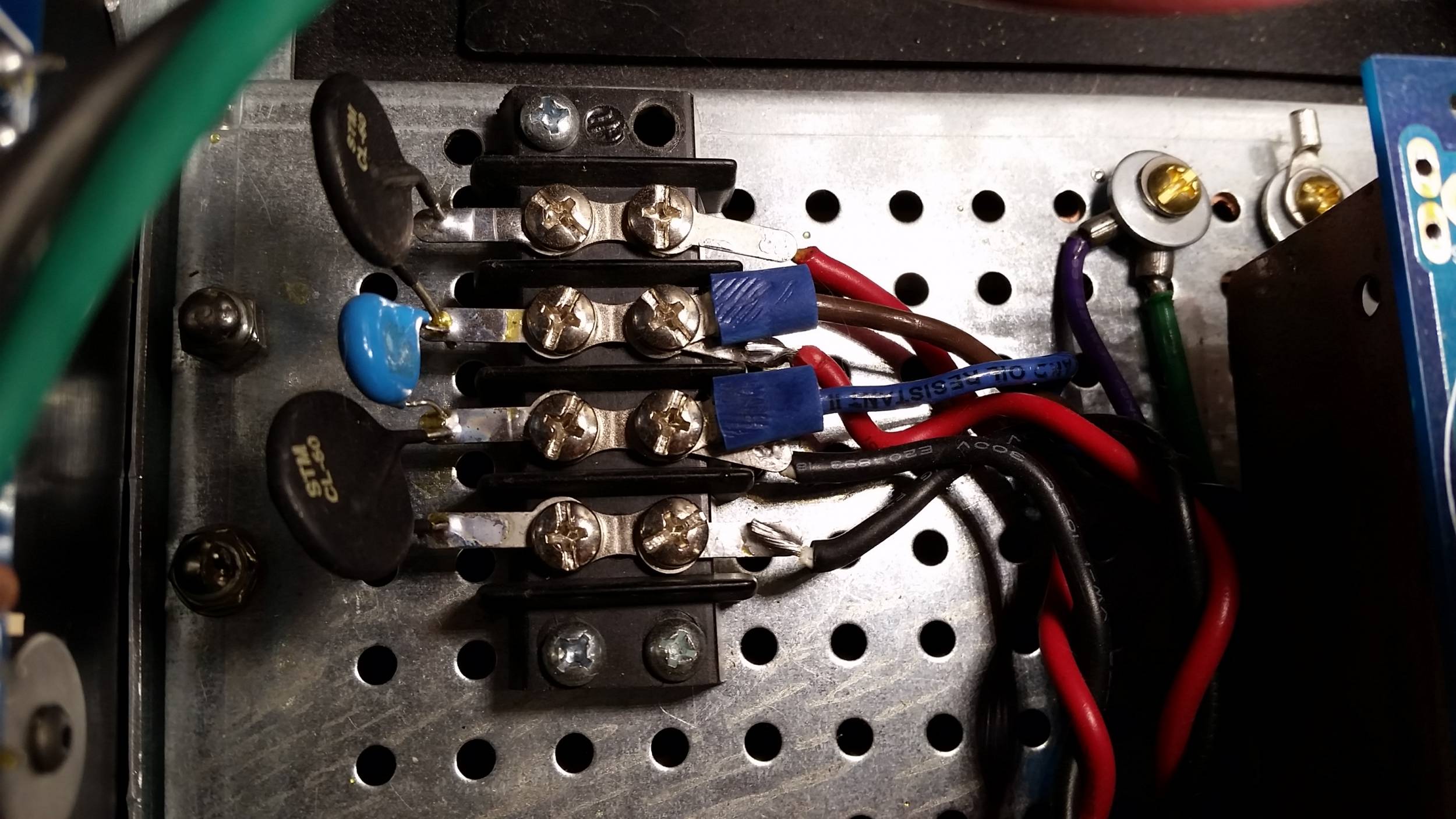
Here is where the thermistor is not mechanically fastened, only soldered (not approved by some that state a solder point can fail, and it's not a good one to fail) to a bridge between the two sides of the V3 PSU hoping for the most neutral ground as in not favoring one side or the other. If electricity is lazy and takes the easiest path, I was hoping to avoid having one side grounded "better" than another. Yes, the thermistor leads are very close to the IEC, but made the assumption the PTFE sheath around the leads would have prevented contact.
That stuff surrounding the IEC? It's epoxy. For all I know some ran into the IEC? I don't know anything about the epoxy - if it is electrically conductive.

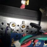
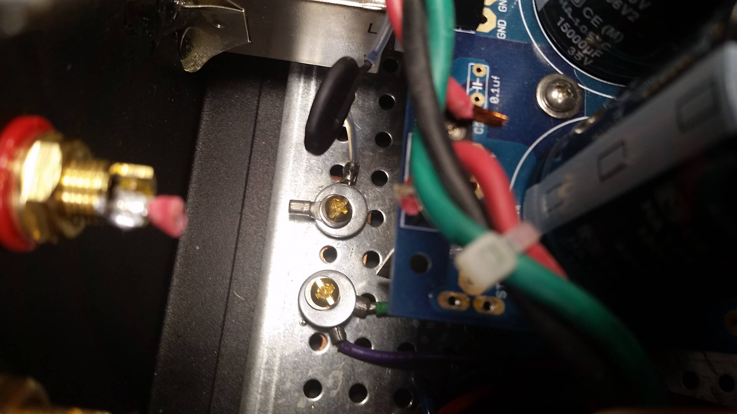
Here is where I tried to bring the ground from the IEC, the shield from the transformer and the thermistor from the PSU to one point. But the wires wouldn't reach. So I cut a strip of copper sheet and put the two as close as possible.
I'm new to this, so if it is not a good idea, let me know. The extra lead attached at the point where the thermistor grounds to the chassis was there from when I thought the wires would reach. With my clumsy fingers working in a tight space, trying to keep washers and bolts together I just gave up and left it there. I figured the brass screws might conduct better than stainless.
OK, so would it be better to bring the IEC ground and transformer ground to the chassis?

So that's where I'm stopping today... the wire I'm waiting on may arrive late today or Monday.
Attachments
I ordered the same Schurter 4304.6090 IEC inlet as sold with the deluxe chassis rear panel kit for the new back panel. They come with a fuse holder that holds two fuses instead of one. I am guessing two are required, originally designed for 250V, and using US 120V one will be for hot, one for neutral? The warning on the cover of the fuse holder states "use only a 250V fuse". On hand I have 4a 125, and 3.1a 250v, and a hardware store nearby with other options.
I wondered about this, too. Looks like you'd just want a fuse in the hot leg so if it blew the unit would be dead. With a fuse in both legs, if the neutral somehow failed the hot leg would still be live. I wouldn't think having a fused neutral that could fail with the hot leg live would be a good situation - but I'm no EE and have never used one of these types of fused switch before.
I apologize for the large attachments above. I should have reduced to a reasonable level, rotated, left out the blurry, etc.
Using a jumper for neutral seems has been suggested for those of us using 120V.
I'm loosing my mind because I have misplaced the fuse holders. Electrical tape and aluminum foil ... just kidding... maybe.
I wondered about this, too. Looks like you'd just want a fuse in the hot leg so if it blew the unit would be dead. With a fuse in both legs, if the neutral somehow failed the hot leg would still be live. I wouldn't think having a fused neutral that could fail with the hot leg live would be a good situation - but I'm no EE and have never used one of these types of fused switch before.
Using a jumper for neutral seems has been suggested for those of us using 120V.
I'm loosing my mind because I have misplaced the fuse holders. Electrical tape and aluminum foil ... just kidding... maybe.
How do I test for shorts using a MM?
There is nothing visible to my eyes.
Using the diode test feature, with only ground connected between the F4 PCB and the power supply I get no tone indicating connectivity between any MOSFET leg and the chassis.
With V+ and V- wires connected I get a tone. (I haven't had the AC power connected for week and have attempted to drain capacitors using a resistor)
But I’m missing something and not getting replicable results.
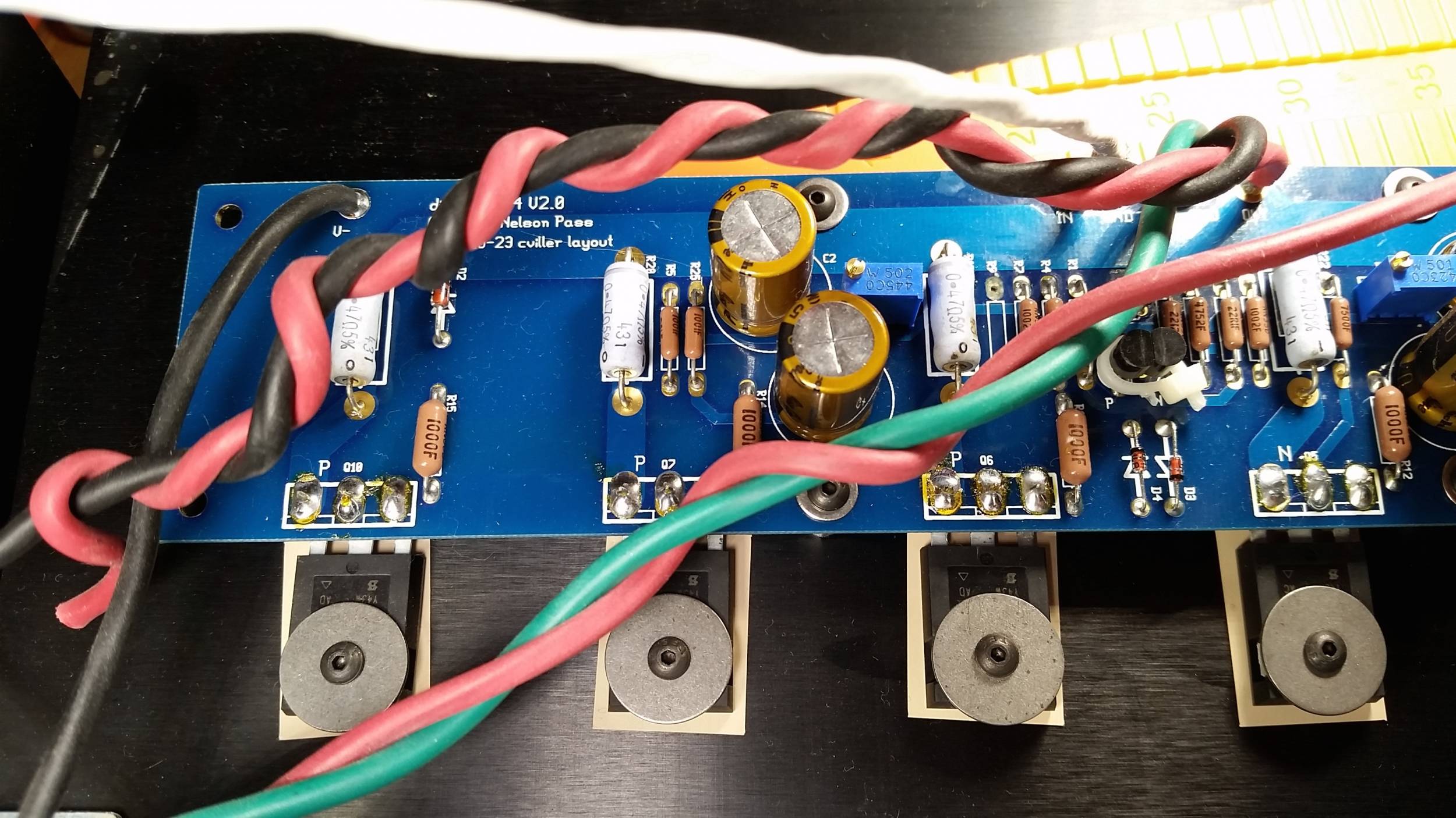
I was prepared to state “each tone is different for each leg”, but as I go through and try to verify the tone changes. Example, short blip on P channel left and right legs, constant blip on center leg. No blip on N channel third leg (a viewed with MOSFET installed on the board. Go through and test all, then I cannot replicate the same results. Sometimes no tone - but it seems to be consistent that all three N channel will behave the same, maybe it goes for P channel as well.
I have a ground connected from the PSU board ground to the safety earth screw of an electrical outlet. The AC from the wall is not connected.
There is nothing visible to my eyes.
Using the diode test feature, with only ground connected between the F4 PCB and the power supply I get no tone indicating connectivity between any MOSFET leg and the chassis.
With V+ and V- wires connected I get a tone. (I haven't had the AC power connected for week and have attempted to drain capacitors using a resistor)
But I’m missing something and not getting replicable results.
I was prepared to state “each tone is different for each leg”, but as I go through and try to verify the tone changes. Example, short blip on P channel left and right legs, constant blip on center leg. No blip on N channel third leg (a viewed with MOSFET installed on the board. Go through and test all, then I cannot replicate the same results. Sometimes no tone - but it seems to be consistent that all three N channel will behave the same, maybe it goes for P channel as well.
I have a ground connected from the PSU board ground to the safety earth screw of an electrical outlet. The AC from the wall is not connected.
Using a jumper for neutral seems has been suggested for those of us using 120V.
Yeah, I just bypassed the whole shebang on the neutral side after mulling it over.
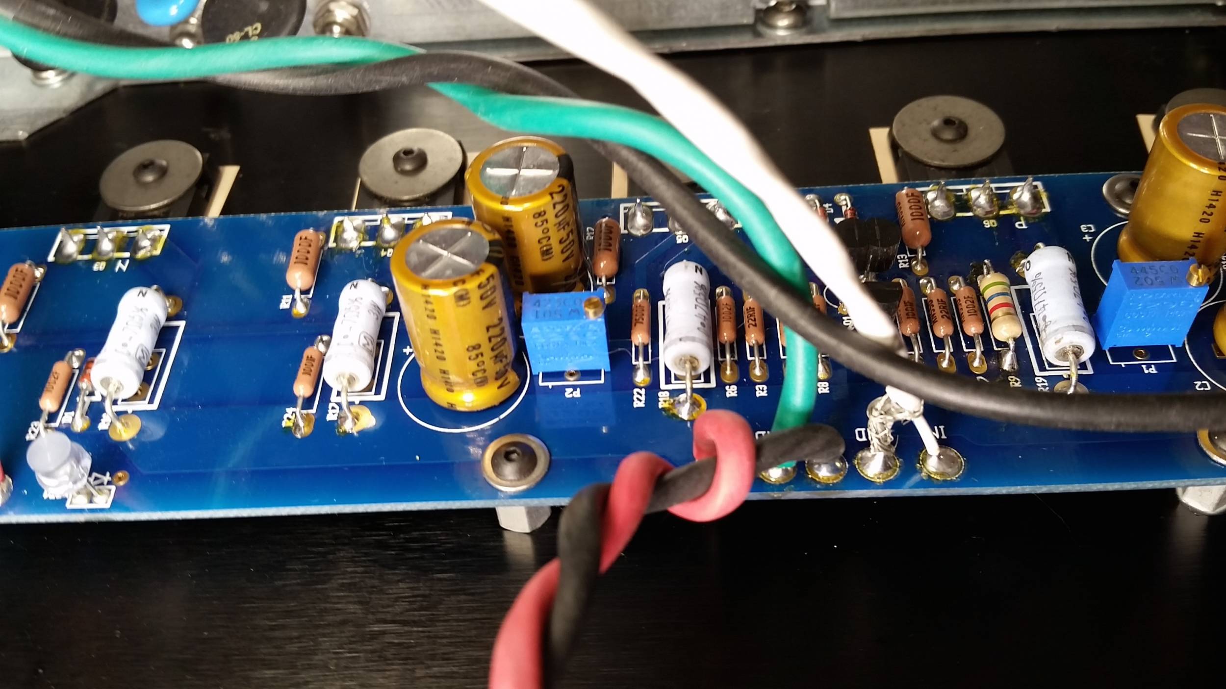
Worked on one channel before rewiring.
Resistance across a source resistor read 1.3 or 1.4 ohm.
Applied power to one channel.
With about 4.6K in R9 the voltage started out at 1.3V, potentiometer P1 at far counterclockwise. Waited an hour, temp went from 72F to 85F.
Turned P1 until voltage climbed to 2.0 across one of the 3W resistors.
Checked voltage at ends of output to speaker terminals and measuring 13.5V. (?) I can turn P2 all the way in either direction and it only changes by .1 volt, maybe .2
Heatsinks at 97 on the outside, 96 on the inside, same temp as the MOSFET's.
I don't have the chassis sealed up, just wanted to see if I could get in the ballpark.
DC across output may be dipping, varying around 13.13 currently
Room temperature 70F.
15 minutes later, 1.5 hours after starting heatsinks at 100F
DC across output has dropped below 13V, haven't changed P1 or P2.
Temp continues to slowly rise, voltage continues to slowly drop.
Voltage across 3W resistor hasn't changed... maybe risen to 2.1, but that's using a different DMM.
15 minutes later, 1.5 hours after starting heatsinks at 100F
DC across output has dropped below 13V, haven't changed P1 or P2.
Temp continues to slowly rise, voltage continues to slowly drop.
Voltage across 3W resistor hasn't changed... maybe risen to 2.1, but that's using a different DMM.
you see , simple equation I=U/R is telling you that with 2V across one source resistor of 0R47 , there is 4A flowing
that's waaaaay too much , considering that Iq is in range of ,how much ? ..... maybe 0.5A per mosfet vertical pair ........ giving approx 250mV across source resistor
and you dial it up to 2V??
go back to reading , leave amp to rest
that's waaaaay too much , considering that Iq is in range of ,how much ? ..... maybe 0.5A per mosfet vertical pair ........ giving approx 250mV across source resistor
and you dial it up to 2V??
go back to reading , leave amp to rest
Powering off.
100F temp outside of heatsink, MOSFET about the same... more likely my thermometer doesn't read the surface the same.
It was at 12.5V when powered off.
LED's are still on and draining , down to 4V after about 2 minutes and dropping.
I have a 3.1 amp slow blow fuse which didn't blow.
I've been feeling my IQ has been moving to the left side of the bell curve.
I'll review again tomorrow, and check DMM's and be sure the decimal is in the right place. I can only imagine it was adjusted to 0.2 and that was a typo.
- Home
- Amplifiers
- Pass Labs
- A guide to building the Pass F4 amplifier