Are you measuring the bias for the f4 in the correct place? It should be around 0.2v or 200mV. At 2v you are likely to be running the thing way too hot. Probably fatally so. Check post 1 of this thread.
Are you getting 120 degrees Celsius or Fahrenheit?
125 Fahrenheit would be OK. Celcius not so much. The heat sink shouldn't get hotter than 50 or 60 degrees Celsius. You should be able to hold your hand on it for 10 seconds as a rule of thumb.
It should also take about an 30 minute to an hour to warm up. If it's getting hot in a couple of minutes I think the bias is way too hot.
I wouldn't think that the preamp gain would affect this. But it may be worth checking your preamp for dc offset at the output and that the volume control doesn't affect that. More gain from the preamp should only mean that the f4 is driven to full volume sooner on the volume dial.
Fahrenheit.
I have once again misplaced a decimal. It takes 20 minutes to get warm, may start listening quietly at 30 minutes and try to wait an hour before going loud. I can keep my hands on the heatsinks without concern of burning, only discomfort.
My test for DC offset on the preamp, mostly on startup and shutdown there is wide voltage swing. I'm not testing with signal going through. Hoping that is safe, a few years ago I made smoke trying that, maybe I shorted the test leads? I assume is the coupling capacitors charge and drain. Generally I'll see a surge of 5V, an open loop notification, maybe 10V for a flash, then dancing between less than +/-0.04V with most time spent below 0.01V.
...getting over fear of measuring with signal.
Now letting things warm up again with a DMM measuring voltage at preamp output. It is more stable with signal (measuring problem channel), closer to 0.001v. With my less precise DMM I was getting 0.01-0.02 v DC offset on the F4 problem channel and 0.01 v DC on the one that plays nice. I'll play around with combo's but a little worried about testing at the point where things go bad.
I don't have an attenuator or volume control, using the computer.
Last edited:
If you swap the left and right channels of the preamp going into the f4 does the fade fault change to the other side?
If so that fault is in the preamp.
I'm a bit surprised that the left heatsink is so much hotter than the right. Maybe worth checking component values of one output board against the other.
If so that fault is in the preamp.
I'm a bit surprised that the left heatsink is so much hotter than the right. Maybe worth checking component values of one output board against the other.
speakers
Want to buy some speakers?
Measuring ohms across speaker terminals, "open loop" for suspect channel.
The "good" channel is reading 1.5 M (?) ohms and climbing as I leave the meter hooked up. Now at 2.7 M ohms after 10 minutes.
I don't get this, the cheaper meters will not read anything.
A second pair of speakers measured a more expected 3.7 ohms (no M).
Different speakers, different crossover networks.
I need a beer. Which means it is time to stop playing with electricity.
Jeffs: Your speaker might have a capacitor in series, maybe a large bipolar elko, and that would explain your dc ohm readings. You could take it apart to confirm, but you probably have enough to do with your amp. Keep at it though, the F4 should be a great sounding amp when you sort it out, which will be soon.
Yes, the F4 sounds great!
I moved the speaker issue to a different section.
http://www.diyaudio.com/forums/multi-way/305643-infinity-rs-iiib-strange-measurements-amp-stress.html#post5028421
I moved the speaker issue to a different section.
http://www.diyaudio.com/forums/multi-way/305643-infinity-rs-iiib-strange-measurements-amp-stress.html#post5028421
For those who built with the 4u deluxe chassis what do you bias at? The build guide for the 5u suggests 300mv.
Mine seems to drift and recently seems to be running on the cold side. I think last time I biased it I took it to 220mv but I think it will go a bit hotter safely.
Mine seems to drift and recently seems to be running on the cold side. I think last time I biased it I took it to 220mv but I think it will go a bit hotter safely.
I briefly ran my F4 in a fan cooled 120mm tall chassis at 360mV.
The heatsinks stayed below 45C even during the hot of the summer.
I was essentially running "silent" rated computer fans at only 9V which made them even quieter.
An 18V zener diode off of each rail for each heatsink's 2 series linked fans worked like a champ.
I have since pulled the fans and run standard 200mV bias.
Measured on the outside of the 4u x 300mm heatsink with a thermometer I haven't calibrated, 200mv is ~50c /119f - 123f with room temperature of 22.2c / 72f. It is usually warmer in the house, that was a luxury of late winter.
I don't know why you are getting away with 5 degrees Celsius lower, maybe it is that I'm running rails with a transformer with 20v secondaries vs a presumed 18v?
I think I'm using the same thermal interface material you recommended to me some time ago.
210mv is as high as I have gone, for me it is hotter and I backed back down from there.
During the incident mentioned around the first day of spring, (coincidence, I'm being lazy and can't see post number, only the date) the temperature would rise quickly above 50c. The first time I caught it it was 62c+ (145f). I'm listening at lower levels for the time being.
5U or 400mm deep 4u if I had hindsight.
I'm going to have someone look at it to see how distortion is, how much signal I'm feeding it, other things that are over my head... and replacing the electrolytic caps in speakers.
I liked the sound more before I switched preamp tubes from 6SN7's to 6SL7's for more gain. If only discussing the First Watt, I enjoyed that First Watt more before the change to the pre.
Both air conditioner and a box fan are roaring right now, and I don't even have an amp on
I've been listening.........
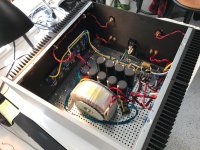
well , tidy arranged , so I can't see any possible culprit
however , few questions :
- origin of input JFets ?
-mosfets properly matched ? did you checked voltage across all source resistors , to be sure in actual equality of their Iq ?
-did you checked equality of mosfet temperatures - measure of their equal torque and temp. transfer interface ?
considering that your sps are 4-ohmish , up to (say) 15W amp is in pure class A envelope and up to there , heatsinks are even cooler than in silence ; above that , there is AB (KLUNK!) transition and heatsinks are going to be warmer
again , no reason to be feared even of 60C at heatsinks , as long you're sure in your build and as long sound quality isn't worse without known reason (which could be clipping)
when you achieve proper thermal and sound quality behavior , you can always try that one amp in balanced mode , feeding just one speaker
I believ that should give enough info about difference between 50 vs. almost 200W at 4 ohms
Measured on the outside of the 4u x 300mm heatsink with a thermometer I haven't calibrated, 200mv is ~50c /119f - 123f with room temperature of 22.2c / 72f. It is usually warmer in the house, that was a luxury of late winter.
Sounds perfectly reasonable to me. I run mine at 225mv and its usually around 50-55c on the headsinks, been running fine for a couple of years. .. i cant vouch for the absolute accuracy of my thermometer though.
IRFP240 &9240 are rated at max 150C. To be safe Firstwatt recommends 55C as they should, a child or wimpy adult may get burned. Brave diyer's are not afraid to go higher. Consensus is the higher you go the better it will sound until it catches fire. I would assume higher temp shortens life. No big deal really for diy'er, replace a few mosfets. How far is one willing to go for best sound. As Zen stated, I am not afraid of 60C or even 65C with my BAF-1. My F4 runs 50C to 55C standard bias. Maybe someone will play with highest bias vs sound before smoke and let us know the result.
Last edited:
I had a few beers while replying over a week ago but looks like I forgot to post it.
A trusted board member - Alex from Israel. Parts were confirmed by a local board member who has more tools / toys. He says they are nicely matched and measuring as BL grade Toshiba parts should test.
Ehhhh, I may have mixed "sets" - as in I ordered enough for four boards. Result is I may have the troublesome board's P channel and N channel not as precisely matched as intended. I measured a small difference across N and P channel source resistors on the same board. The N channel and P channel by themselves were consistent. I tried measuring from one side of one resistor to the other side of the other two resistors and had exact matches as far as measuring bias voltage. Didn't try measuring from N to P because it didn't feel too smart :roll eyes:
The interface is Tgard 5000, it seems sturdy. No signs of wear. I replaced them the first time I removed the MOSFET's from the heatsinks but don't see a reason to do it again, they appear intact.
I don't see anything in there about where I came up with 11 inch pounds, maybe I'm talking out of the wrong hole.
As far as ids matching goes, third party mentioned said they were very good.
There is a little difference in temperature, but nothing more than 3 degrees f with my limited ability to measure temperature. (not going hands on to measure inside the chassis, electricity safety jokes are not a good idea so I'll drop it for now)
KLUNK! is an accurate description, but not really noticing a drop in temperature when running with sound vs idle / preheating. Maybe because I'm on my couch thinking "awesome!" until the crash happens. Not really, I learned what would kill it and would measure as it was expected to happen.
While I do have the manual in front of me, I'm not really sure how to wire it.
Balanced single channel would be the two + outputs are tied at the amp and one cable run to a speaker, same with the “other” which I’m not sure to call “ground” or “-“?
The F4 has been running for a few hours now, first attempt at overheating it said 119f for right, 128f for left. Left is one with differences in MOSFET P / N. - my fault, not seller.
I wrote the above over a week ago, since then I had some bad sound coming through the left tweeter, grabbed the laser thermometer and it read the opposite temperatures, lower on left channel. I increased volume more, let it continue to run then had increase on left channel. Maybe I’m being more cautious with music selection and volume. Only thing I have changed is using bare wire in the amp and speaker terminals instead of cable ends.
I might learn something one of these days.
If temperature calibration is using hands as Papa says, I’m running a lot cooler. It’s usually like a nice warm heating pad.
Back to the dropping out of class A - would more bias prevent that? I don’t have a scope / distortion analyzer obviously.
Going to put the plinth making tools back for the time being and get to soldering the other set of boards back together in a couple of days.
well , tidy arranged , so I can't see any possible culprit
however , few questions :
- origin of input JFets ?
A trusted board member - Alex from Israel. Parts were confirmed by a local board member who has more tools / toys. He says they are nicely matched and measuring as BL grade Toshiba parts should test.
-mosfets properly matched ? did you checked voltage across all source resistors , to be sure in actual equality of their Iq ?
Ehhhh, I may have mixed "sets" - as in I ordered enough for four boards. Result is I may have the troublesome board's P channel and N channel not as precisely matched as intended. I measured a small difference across N and P channel source resistors on the same board. The N channel and P channel by themselves were consistent. I tried measuring from one side of one resistor to the other side of the other two resistors and had exact matches as far as measuring bias voltage. Didn't try measuring from N to P because it didn't feel too smart :roll eyes:
I did not use a torque wrench, but have a fairly good idea of what 11 inch pounds feels like. I had a machine shop (which primarily makes part for local semiconductor plants) drill the holes in the heatsinks, I bought the drill bits for them to drill a 65-70% fit vs the tighter 75% fit tolerance. I chose this because I've had problems with taps purchased post 2010 and wanted to make cutting threads as easy as possible, not seeing an advantage to the tolerance of the threads. Earlier in life I had training on how to tap very expensive parts. I don't think the mechanical fastening is the issue. At the same time, this does scream short! to most people that understand the electronic side.-did you checked equality of mosfet temperatures - measure of their equal torque and temp. transfer interface ?
to be sure in actual equality of their Iq ?
The interface is Tgard 5000, it seems sturdy. No signs of wear. I replaced them the first time I removed the MOSFET's from the heatsinks but don't see a reason to do it again, they appear intact.
I don't see anything in there about where I came up with 11 inch pounds, maybe I'm talking out of the wrong hole.
As far as ids matching goes, third party mentioned said they were very good.
There is a little difference in temperature, but nothing more than 3 degrees f with my limited ability to measure temperature. (not going hands on to measure inside the chassis, electricity safety jokes are not a good idea so I'll drop it for now)
considering that your sps are 4-ohmish , up to (say) 15W amp is in pure class A envelope and up to there , heatsinks are even cooler than in silence ; above that , there is AB (KLUNK!) transition and heatsinks are going to be warmer
KLUNK! is an accurate description, but not really noticing a drop in temperature when running with sound vs idle / preheating. Maybe because I'm on my couch thinking "awesome!" until the crash happens. Not really, I learned what would kill it and would measure as it was expected to happen.
again , no reason to be feared even of 60C at heatsinks , as long you're sure in your build and as long sound quality isn't worse without known reason (which could be clipping)
when you achieve proper thermal and sound quality behavior , you can always try that one amp in balanced mode , feeding just one speaker
I believ that should give enough info about difference between 50 vs. almost 200W at 4 ohms
While I do have the manual in front of me, I'm not really sure how to wire it.
Balanced single channel would be the two + outputs are tied at the amp and one cable run to a speaker, same with the “other” which I’m not sure to call “ground” or “-“?
The F4 has been running for a few hours now, first attempt at overheating it said 119f for right, 128f for left. Left is one with differences in MOSFET P / N. - my fault, not seller.
I wrote the above over a week ago, since then I had some bad sound coming through the left tweeter, grabbed the laser thermometer and it read the opposite temperatures, lower on left channel. I increased volume more, let it continue to run then had increase on left channel. Maybe I’m being more cautious with music selection and volume. Only thing I have changed is using bare wire in the amp and speaker terminals instead of cable ends.
I might learn something one of these days.
If temperature calibration is using hands as Papa says, I’m running a lot cooler. It’s usually like a nice warm heating pad.
Back to the dropping out of class A - would more bias prevent that? I don’t have a scope / distortion analyzer obviously.
Going to put the plinth making tools back for the time being and get to soldering the other set of boards back together in a couple of days.
considering all tolerances involved in measurement ( differenes between mosfets , between source resistors , DVM tolerance) , you're good in 10% bracket
regarding temperature , 55C (131F) at top of heatsink is normal temp for FW amps
regarding parallel or bridged (balanced) operation of F4 - it's all covered in F4 article/manual , with proper graphical info
things are simple - if you need more juice in current domain (lower impedance speaker than "common standard" of 8R) - go for parallel
if you need more juice and spks are 8-ohmish , that would be certainly in voltage domain - then go bridged (balanced)
- Home
- Amplifiers
- Pass Labs
- A guide to building the Pass F4 amplifier