uh, yeah...
I dialed it to 0.2V
turned it back on for 5 seconds to see it climb to 0.191 volts across source resistor.
and - what is output offset (DC voltmeter , probes between black and red output terminals , no load on output) ?
12V or 1.2V ??
if later , all you need is fiddle with P2 (ref to sch in post #1)
If you have a bench supply capable of decent current you could hook that channel up directly to the board and gradually increase the rail supplies (well under what they're meant to be) whilst you figure out where it's going wrong reducing the risk of frying your mosfets.
/* probably void now as new info was posted whilst writing but the thought may be relevant....
Did you just measure one source resistor at 2v? My hunch is that you've got one set of 3 at 2v and the other set at something more appropriate.
*/
If you don't have a bench supply try using your light bulb limiter with a low wattage bulb and try to work out why there is such an imbalance.
Am I right in thinking the other channel is OK?
If so compare voltages. Don't worry if the amps not getting warm with the tester in. That's a good thing! But keep an eye on all the mosfets in case just one is getting hot.
Last edited:
I appreciate the responses.
No bench supply here, have three home-made controllers but doubt they are suitable...
another topic for a different section.
Back to my IQ left of the bell curve...
This morning I attached the leads across the source resistor and have to wonder if I had the leads attached backwards yesterday. Could I have adjusted for negative[/U] -0.13V? I turned down the pot all the way counterclockwise and never got to positive voltage.
Maybe R9 should have been left at 10K.
Yes, the voltage on the outputs was at +12.85V this morning, same place it was after almost two hours of warming up yesterday. Being that it took almost two hours to slowly climb down from 13.5ish I wonder if the change was a result of parts breaking down. I'll stop wondering because I have no idea what I'm talking about.
This is probably the same channel which climbed to really ******** hot in a matter of two minutes, so possibly everything was toasted. That was back in February when I put it away since winter was over, err never arrived last year.
Heading out of the house for a few hours, may try going back to R9 value of 10K... and if that doesn't work I'll have a whole bunch of parts / equipment to sell or possibly hire someone to build one of the F4's
during first power-up , when nothing is set , you need to see voltage across one of source resistor in vicinity of intended , and output offset voltage up to few volts (either positive or negative)
if outout offset voltage is anything above that , something is toasted or not connected or there is another type of mistake (wrong value etc. )
as I see your problem , there is nothing about value of R9
are you able to start again ...... dunno ... only you can answer that
try finding someone with more experience to help
Thanks for the assistance.
I'm calling that board a loss - or to be parted out later.
Good news is the other channel seems to be behaving. A very ugly patch job to get solder to flow, but I seem to have R9 with a value of 6K... Somewhere between the original 10 and whatever I may have had in there before. There is a little negative DC on the output measured from the solder pads. It started to warm up at a reasonable rate.
Calling it a night.
Don't forget gain...
My mechanical switches on my old preamp got so noisy that I recently
acquired a new preamp, and I made sure it can swing quite a bit of
voltage.
Of course, being the idiot I am, I completely neglected the issue of gain.
With 10dB gain, and 2.1RMS max from my player, I think the max
power I'm getting from the F4 is less than 6W into 8 ohms.
I'm in a small room and the new combo sounds great on music.
With movies I do wish for a bit more gain.
Dennis
Eventually a new preamp will be needed since this one does not have adequate
voltage swing for the F4 (max 10V RMS).
My mechanical switches on my old preamp got so noisy that I recently
acquired a new preamp, and I made sure it can swing quite a bit of
voltage.
Of course, being the idiot I am, I completely neglected the issue of gain.
With 10dB gain, and 2.1RMS max from my player, I think the max
power I'm getting from the F4 is less than 6W into 8 ohms.
I'm in a small room and the new combo sounds great on music.
With movies I do wish for a bit more gain.
Dennis
F4 Progress
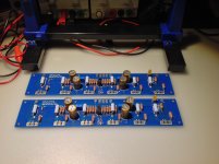
I've started building an F4. Today I've been able to stuff one channel. This represents ~2 hours of work for me. I think this is the easiest part of the project. The part I find least enjoyable is ordering parts.

I used KOA Speer MF series resistors this time. These resistors are color coded which makes them a pain if you want the bands all facing the same direction. All other parts need are in the house. Chassis will be delivered Monday and then goes to the machine shop. I hope to carve out enough time to finish this project and be listening to it in two weeks.
On a side note I found these at Parts Express while shopping for RCA inputs. They are very useful!

I'm saying all this to basically bump this thread to the top, I refer to it often.
I've started building an F4. Today I've been able to stuff one channel. This represents ~2 hours of work for me. I think this is the easiest part of the project. The part I find least enjoyable is ordering parts.
I used KOA Speer MF series resistors this time. These resistors are color coded which makes them a pain if you want the bands all facing the same direction. All other parts need are in the house. Chassis will be delivered Monday and then goes to the machine shop. I hope to carve out enough time to finish this project and be listening to it in two weeks.
On a side note I found these at Parts Express while shopping for RCA inputs. They are very useful!
I'm saying all this to basically bump this thread to the top, I refer to it often.


I recently built the F4 to add to my other builds. I can understand now why 6L6 likes this amp so much. I have a number of pres to use both tube and SS and the pre does change the sound. From the description of the amp being basically neutral one is listening to the sound of one's pre. With my SRPP tube amp the sound is very tube like and with one of my SS pres the sound is more dynamic and quicker. I like both sounds depending on my mood at the moment. I took more care matching the mosfets on this build and I like to think I have been rewarded with a cleaner sound. Not having a distortion analyzer this is just subjective.
One question for more knowledgable members. What is the advantage of more stages of mosfets as the Passlabs amps? I have read some info on this topic but my memory needs to be refreshed.
One question for more knowledgable members. What is the advantage of more stages of mosfets as the Passlabs amps? I have read some info on this topic but my memory needs to be refreshed.
Maybe a better way to put it is the F4 vs the BA-2 being they are very similar. What is the advantage having 3 extra pair of mosfets. I have been considering building a true BA-2 with the BA-3 front end and 6 pair of output mosfets. With a heftier PS section. I suppose one could just add 3 extra pairs to a F4. More heatsinking of course.
Last edited:

- Home
- Amplifiers
- Pass Labs
- A guide to building the Pass F4 amplifier