Hi Michael
I completely agree.
Yes, grid current is well modelled now I have to say that the circuit reacts very well. The driver is not loaded I think because
of the wonderful behavior of the 845 in this respect.
Things deteriorate a bit with the NF (pots. set to 500 Ohm).
I do not know well why, still investigating. Maybe the fact is due
to ...
the increased load (decreased resistance) that 845s see
(for instance from 11.5k/2 to 5k). This, moreover, causes
a premature shift in class B with increased dist.
I am at home now, tomorrow I'll send you the cir.
It's a pleasure, Michael. This on line collaboration intrigues me a lot.
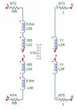
The LL1620 has been implemented as follows
bye
Federico
if small amounts of local type were included for reasons of dynamic balance or other reasons, I think it could be OK. Only listening tells.
I completely agree.
Have you modelled the transistion to grid current yet? How does the driver stage react? The circuit as a whole? Would the feedback as you've drawn above have an effect on this aspect of the performance?
Yes, grid current is well modelled now I have to say that the circuit reacts very well. The driver is not loaded I think because
of the wonderful behavior of the 845 in this respect.
Things deteriorate a bit with the NF (pots. set to 500 Ohm).
I do not know well why, still investigating. Maybe the fact is due
to ...
You said, "This kind of NF decrease
the resistance seen by each tube"
the increased load (decreased resistance) that 845s see
(for instance from 11.5k/2 to 5k). This, moreover, causes
a premature shift in class B with increased dist.
I am at home now, tomorrow I'll send you the cir.
Also Federico, many thanks for the great efforts you have expended...
It's a pleasure, Michael. This on line collaboration intrigues me a lot.
The LL1620 has been implemented as follows
bye
Federico
Attachments
Hi Michael
with your schematic static and dynamic
balancing are interconnected.
But I want separated adjust pot
since the cause of unbalancing may be different
Tube differences affect mainly static balance,
while trafo asymmetries directly influence
dynamic balance.
Only one ( of the two) pots ( dyn. bal) have to be adj.
only the right one. the other is left ot zero res
thus no NF in that part. NF only where it is
needed. May be this can be changed , I have not
think on , to utilize only one dyn balance pot.
Federico
with your schematic static and dynamic
balancing are interconnected.
But I want separated adjust pot
since the cause of unbalancing may be different
Tube differences affect mainly static balance,
while trafo asymmetries directly influence
dynamic balance.
I have used that layout to minimize NF use.Did you have the dynamic feedback pots set symmetrically when you modeled them?
Only one ( of the two) pots ( dyn. bal) have to be adj.
only the right one. the other is left ot zero res
thus no NF in that part. NF only where it is
needed. May be this can be changed , I have not
think on , to utilize only one dyn balance pot.
Federico
dynamic unbalance
Hi Federico,
I got the files OK and have played a little bit already. Very nice.
For the dynamic unbalance, my thinking was that the AC current through the shared R (closest to VR tube) would be zero in the case of a dynamically balanced circuit, but a feedback voltage would develop in the unbalanced case which would work in opposite on the tubes to acheive balance. No? The static balance resistance is bypassed so that it does not effect dynamic balance.
Michael
Think about a statically unbalanced but dyn balanced case.
I adjust one pot to restore correct current values.
But making so I will change the load of one tube in
respect to the other and it will dynamically unbalance the circuit.
In your cir, for AC current, one tube see a part of one static pot res in parallel to part of the dyn pot res.
My static pot do not change the load of the tubes
because of the capacitors to ground. The AC current
does not see those pots.
Federico
discussion point
Hi Federico,
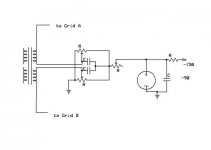
I know the circuit had some problems with the back end of the voltage divider, I just posted it as an example for discussion. What would happen if the 470k resistor between grids of the 845 was replaced by two separate resistors to ground, so there would be some small static current through the bias setting resistor. Then the voltage divider could be removed and replaced by a bypassed variable resistance to set the static without effecting the dynamic balance?
What is the purpose of the 0.5 nF capacitor between the grids of the 845s?
Michael
Hi Federico,
I know the circuit had some problems with the back end of the voltage divider, I just posted it as an example for discussion. What would happen if the 470k resistor between grids of the 845 was replaced by two separate resistors to ground, so there would be some small static current through the bias setting resistor. Then the voltage divider could be removed and replaced by a bypassed variable resistance to set the static without effecting the dynamic balance?
What is the purpose of the 0.5 nF capacitor between the grids of the 845s?
Michael
What is the purpose of the 0.5 nF capacitor between the grids of the 845s?
To avoid a resonance, apeak in the frq. responce probably
due to the interaction of the grid capacity with
the 1660 trafo. I do not know if it is a real thing.
Note also that parassitic capacitances are not modelled
in tha trafos.
What would happen if the 470k resistor between grids of the 845 was replaced by two separate resistors to ground, so there would be some small static current through the bias setting resistor. Then the voltage divider could be removed and replaced by a bypassed variable resistance to set the static without effecting the dynamic balance?
Something like this can be done . I will try.
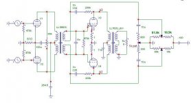
In the meanwhile here is a version of the adj cir that avoid
one pot but introduce some NF also when things are perfectly
simmetric since we have 500 Ohm in series.
Bye
Attachments
balancing pot
Yes, I thought about this case, too. Also, I have not had a chance yet to figure out how the feedback affects the output impedance to the load. Does it have any beneficial effect? Now a practical question, how would one monitor the dynamic balance, so that the user could adjust it without sophisticated equipment? I guess this also applies to the 6SN7 balance pot.
Still many problems to solve with my plan, not involving the signal path, but the things like turn on delays and safety, etc. Lots of work.
Michael
Hi Michael
the simplest way to dynamically balance the cir
is to use a sound car like soundblaster
and to minimize even order harmonics.
It is not a sophisticated equipment.
An alternative method is to minimize
rms current trough B+ supply.
It is not the same thing, but it is
a good approximation.
Bye
Federico
dynamic balance
Hi Federico,
For myself I know how to balance with the equipment I have. I was just thinking of how one could "build in" a simple balance meter, like a bias meter for static bias. The amp won't be in my possession after it is built, I am building it for a friend. I wonder if you could use an eye tube, with the out of phase plate signals being summed to indicate balance by the closing or opening of the eye? One could use a test tone from a CD to generate the signal.
Almost have the breadboard setup again. Hopefully, will be able to give a fire up tomorrow.
Michael
output z
Hi Federico,
You've found the other reason I thought a little feedback might be a good thing. Where or how do I get to this value in MCap? Also, the LL1620 file shows up as a paint shop pro file, is there some way I can read what is in that file or is it not text?
Still thinking about a way to get an eye tube to display balance.
Getting the breadboard back up has proved to be a bit more of a pain in the butt than I had hoped. I've decided to completely rebuild the frontend connections so that I will have totally separate supplies for the 6SN7 and the 12B4s. Those plus the B+ supply, the negative bias supply and the filament supply means I have to take a little more care with my hookups to make sure they are right.
Michael
hi
If you are referring to the LL1620.mac and LL1660S.mac
file, yes, they can be read with the notepad but it is difficult to understand something in this way. It is by far better to read them with Mcap: File/Open/filetype =Macro.
Excuse me Michael but I never saw an eye tube.
How does it work?
A question: You say me to assume DC secondary resistance of
the 1620 as 0.2 ohm and, if you see the LL1620.mac, I have
done so ( 0.1+0.1). But I saw the pdf Lundhall file reports
an "average resistance" of 0.4 Ohm. I am confused.
Does it depends on the kind of connections ( A,B, etc.)?
to simulate output res measure: substitute the output load
( 8 Ohm res ) with one of the two voltage sources.
remember its name, for instance V27.
Disconnect the other V source and put it at groud somewhere.
put at ground also the load res. (Mcap does not work is
a component is not grounded, at least indirectly).
Then run AC analysis on the Y expression V(V27)/I(V27).
Adjust the y scale to see something.
Ciao
Federico
Also, the LL1620 file shows up as a paint shop pro file, is there some way I can read what is in that file or is it not text?
If you are referring to the LL1620.mac and LL1660S.mac
file, yes, they can be read with the notepad but it is difficult to understand something in this way. It is by far better to read them with Mcap: File/Open/filetype =Macro.
Excuse me Michael but I never saw an eye tube.
How does it work?
A question: You say me to assume DC secondary resistance of
the 1620 as 0.2 ohm and, if you see the LL1620.mac, I have
done so ( 0.1+0.1). But I saw the pdf Lundhall file reports
an "average resistance" of 0.4 Ohm. I am confused.
Does it depends on the kind of connections ( A,B, etc.)?
to simulate output res measure: substitute the output load
( 8 Ohm res ) with one of the two voltage sources.
remember its name, for instance V27.
Disconnect the other V source and put it at groud somewhere.
put at ground also the load res. (Mcap does not work is
a component is not grounded, at least indirectly).
Then run AC analysis on the Y expression V(V27)/I(V27).
Adjust the y scale to see something.
Ciao
Federico
eye etc
Hi Federico,
Here is a link to a datasheet for an example eye tube, http://frank.pocnet.net/sheets/021/6/6E5.pdf
Yes, the resistance of the LL1620 secondary depends on the connection used. For 11.5k to 8 ohm connection B is used. Then according to the datasheet the resistance is 0.2 ohms.
I just looked at the transfer function demo in MCap. I calculates the input and output impedance at small signal level. Would this work?
I am almost finished rebuilding the breadboard. I would post a picture of it, but I am afraid an electrical inspector would see it and pay me a visit.
Michael
filament connections
Hi All,
Whoo-hoo, got all the power supplies connected up and turned on and no smoke, yet at least. Currents seem about right, so I think I am cooking with gas.
A question: For the first iteration I am planning to parallel the filaments and use AC on the 845s. Should I connect pin 2 to pin 2 and pin 4 to pin 4, or should I reverse the phase in the two filaments, ie pins 2 to pins 4?
Thanks,
Michael
Michael
Thanks for ray tube data.
I think it does not work, sure not with transformer, maybe it gives the DC resistance. I never succeed to make it works. However it is simple to make as I tell you.
great!
I think it is the same but try exchanging pin connections to see if hum reduces.
What pot Do you use to minimize hum?
Michael,
your input impedance, from old posts, results unacceptably low.
Can you give me precise data about the input trafo, so I can model it?
ciao
Federico
Thanks for ray tube data.
I just looked at the transfer function demo in MCap. I calculates the input and output impedance at small signal level. Would this work?
I think it does not work, sure not with transformer, maybe it gives the DC resistance. I never succeed to make it works. However it is simple to make as I tell you.
Whoo-hoo, got all the power supplies connected up and turned on and no smoke, yet at least.
great!
For the first iteration I am planning to parallel the filaments and use AC on the 845s. Should I connect pin 2 to pin 2 and pin 4 to pin 4, or should I reverse the phase in the two filaments,
I think it is the same but try exchanging pin connections to see if hum reduces.
What pot Do you use to minimize hum?
Michael,
your input impedance, from old posts, results unacceptably low.
Can you give me precise data about the input trafo, so I can model it?
ciao
Federico
input impedance
HI Federico,
In the models done before on the 6SN7-12B4 the input transformer was an UTC A-11. Now for this amp I have Lundahl 1676. This is a link to the datasheet. http://www.lundahl.se/pdfs/datash/1676.pdf
Right now it is hooked up as 1:2+2, but I will probably connect it 2:2+2 in the end.
I haven't worried about such niceties as a hum pot yet. I will have to see if I have anything around I can use.
Also, I am still finishing my negative power supply this morning.
Michael
- Status
- This old topic is closed. If you want to reopen this topic, contact a moderator using the "Report Post" button.
- Home
- Amplifiers
- Tubes / Valves
- 845 PP and Lundahl 1620