Here is a link to our science fair. You can see my amps here;
http://www.visi.com/~asm/Gallery/Gallery_One/SciFair_2003/scifair_2003.html
Chuck
http://www.visi.com/~asm/Gallery/Gallery_One/SciFair_2003/scifair_2003.html
Chuck
Michael,
Lets see if this works. sorry i'm a newbe to diyaudio.com
Chuck
Lets see if this works. sorry i'm a newbe to diyaudio.com
An externally hosted image should be here but it was not working when we last tested it.
Chuck
Ok, now i'm getting the hang of this.
Here is the power supply.
Chuck
Here is the power supply.
An externally hosted image should be here but it was not working when we last tested it.
Chuck
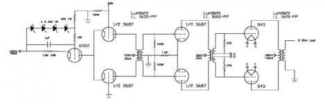
Schematics
Hi Chuck,
Very nice. If I could ask, first of many questions probably, is it necessary or desirable to have separate filament transformers? I am planning to order these today or tomorrow and I still haven't decided whether one bigger one would do?
Where did you hide all the iron? Looks very good.
Why did you decide on the LTP phase split instead of using one of your transformers? What impedance are you running the LL1620 at? Is it really 50mA/pair of 845?
Many more questions floating around, but I will stop here for now.
Once again, nice work and
Thanks,
Michael
Michael,
Well, I used separate windings for the filaments because I wanted to have place to check the tube bias. I found a great transformer from Plitron it was originally designed for a parallel 300B stereo amp. Using one transformer for a mono amp left lots of winding options for the amp.
All the interstage transformers are on a sub chassis supported in the corners.
The 845’s are running at 60ma each tube. I started out more conservative but ended cranking up the bias to 120 ma.
As for the 1620 I have it set for 6K at 8 ohms. This seems to work well with my Quad 63’s.
Chuck
Very cool design Botte..
Some questions, doesnt uncoupling the 845 filaments like
you did kill the common mode rejection of the output stage?
i.e. any noise currents on the filament and bias supplies
would be nulled out in the transformer since they are
common to each phase.
I'd also expect that you could use AC with these filaments
too, since its PP. Did you try that? My guess guess is that
a 10V 10A filament tranny would require some research to
buy the right model... For one, something that big would be
prone to mechanical hum.
Thats a hell of an amp though. Loads of power available.
Pretty much drive anything
-- Jim.
Jim,
Thanks,
Using a split supply, the filaments are sitting only 120 ohms apart and besides giving me a nice point to check the bias it also offers a little degenerative feedback that helps the linerize the output stage.
As for noise this amp is dead silent it has a very quiet noise floor.
Chuck
Thanks,
Using a split supply, the filaments are sitting only 120 ohms apart and besides giving me a nice point to check the bias it also offers a little degenerative feedback that helps the linerize the output stage.
As for noise this amp is dead silent it has a very quiet noise floor.
Chuck
many more questions
Chuck,
Did you try it with AC filaments? I was hoping they would be OK.
Did you try the 1620 in the 11.5k configuration? When I model the 845 in SEAmpCad, there is a significant increase in 3rd harmonic if a 3k transformer is used as opposed to a 6k. I can see where the added power headroom of the 6k hookup would be nice, but it seems at 1kV that you run out of AC headroom just south of 60W anyway. I am planning to try it both ways on the breadboard, but war stories are a good thing.
The Plitron transfomer sounds like a dandy thing! It seems that no matter how I look at it I need 4 or 6 power transformers.
Did you try any other tubes besides the 5687?
Thanks,
Michael
Michael,
I didn’t try the filaments on AC, I’m sure I could give it a try one of these days. It sure would cut some of the heat inside the chassis from the rectifiers.
As for the plate load, I did try it at 11.5K I found that the base was very loose and uncontrolled. It was much better with the 6K load. The next thing I’m thinking about doing to the amp later this year is try a shunt reg. across the -250 V supply. I think this could help the base. Then I could try the 11.5k again?
The Plitron is great, all the windings I needed and it still runs only moderately warm at 750 VA. Oh yea it looks cool too.
Chuck
Bias
Chuck,
What is your bias voltage, about -145? I wonder if you could use something like a 50 ohm resistor on the CT of the filament transformer with 10 ohm running from the top of that to each 845 to get bias reading points and just a touch of cathode bias if AC heaters were used? I did a search on bias metering and didn't turn up much, so I think I will try to start a thread on the subject.
Back to the phase splitting, what advantages do you see from splitting electronically vs with an interstage? Just wondering, since the iron was there anyway.
Later,
Michael
Michael,
I did a differential input to give me more gain.
Yep the bias is around -145V.
You could just bypass the rectifier and remove the filter caps in my circuit and still have the bias test point. Or you could use the center tap with a 10ohm resistor to ground for the test points. I’m not sure it would make any sonic differences, but it might help get some heat out of the chassis.
I think the biggest potential sonic improvement is in regulating the neg bias supply. This is something I have wanted to do since I built the amps. I figured I would use a mos-fet shunt and maybe replace the 2K dropping resistor with a current source. I have found that zener regulated mos-fets make great simple regulators in high voltage applications.
Any thoughts about the operating point of the second stage?
Chuck
driver
Chuck,
Don't know if you have looked at this thread, but this is basically my proposed driver circuit.
On your schematic you show 10mA for the driver stage current. Is that per section or total for both sections? I found a cap from the CT of the 1660 to the top of the cathode resistor had a beneficial effect on sonics in at least some of the configurations I tried. Could you implement the negative supply voltage for the driver section as well as the input to get closer to true current sourced differential? I don't know if that works in this setup or not?
Michael
Michael,
The 10ma is for both sections. I wanted to keep the plate dissipation at about 1.5 watts per section.
The so you think the second section should also have a current source rather than a common cathode bias. It would greatly help the differential gain. Especially if the source impedance of the current source was say 100K. Now I have something else to think about.
What type of effect did bypassing the transformer give, less ringing, earlier roll off or no noticeable effect on the wave form but a sonic effect from a phase response change?
Thanks,
Chuck
Chuck
Nice amp!!!
Just one question, if the amp is built as shown in your schematics your 845 cathodes are not 120 ohms apart. They are tied together by the 4 by pass caps, right? Not that it makes much of a difference, the stage is still very linear at normal output power.
BR,
Anders
Nice amp!!!
Just one question, if the amp is built as shown in your schematics your 845 cathodes are not 120 ohms apart. They are tied together by the 4 by pass caps, right? Not that it makes much of a difference, the stage is still very linear at normal output power.
BR,
Anders
5687
Chuck,
I'm not saying I think the more differential (?) second stage will sound better or give any other benefits, just might be something to easily try, since you already have the power supply. In my limited experience I can't see anything wrong with your operating point. It does seem most 5687 circuits go for more current, but what the? I did try a 5687 in place of the 6SN7 as the voltage amplifier, but I have never tried it in place of the 12B4 as the driver. As volt amp I thought it was not as nice sounding as the SN7. In truth, I did not like either of them as much with the negative supply as when just using a common cathode resistance, but you can look at the other thread if you want more detailed info on that subject.
For the cap, I didn't do a lot of analysis of it's effects. It did lower harmonic distortion in most circuits I tried, but whether that was the source of sonic improvement or not I don't know. I could also be PSRR or noise rejection with the Heathkit variable supply I am using in the breadboard or something completely different. I have done very little analysis since I put the 1660 into the circuit rather than the OPT I was using before to simulate the interstage. I did measure 3rd harmonic once and at that point it was unchanged, with or without the cap. Listening now is more problematic, since I have to hook the interstage to the OPT to the speaker and who knows what the ramifications of that are? It still sounds OK, but not quite the magic it had before. As I mentioned the 845s are in hand now, so by sometime this weekend or next week I will have the whole channel on the breadboard and can resume serious testing/listening.
Michael
- Status
- This old topic is closed. If you want to reopen this topic, contact a moderator using the "Report Post" button.
- Home
- Amplifiers
- Tubes / Valves
- 845 PP and Lundahl 1620