getting to it
Hi Chuck, All,
Funny you should mention remodeling. I was informed by the management of my apt. that I am due for new kitchen cabinets. This has led to a hiatus in design/experimentation on the amp while I clean up my workshop room so that I can move the breadboard into it and empty the kitchen of all it's contents. Pain in the butt. Almost there now so hopefully I will get some work done on it this week.
Michael
Hi Michael
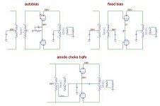
This thread seems quite appropriate to
describe you some topo I am thinking about.
They are very schematized.
In the first you see the classic autobias
config while in the second we have the fixed bias
one.
As you see in both cases plate is at 700V but
in autobias case the cathode is at 100V leaving
us only 600V between plate and cath.
the third pic shows the trafo used as an anode choke.
The capacitor are avoided by lifting the 845 supply,
as you see. Static balance (individual bias adj) can
be achieved by means of a small pot (50R) at the catode.
Dinamic balance can be done by means of a 50k pot between
845 grids (with 3rd leg at ground by a cap).
ciao
Federico
Attachments
Hi Michael
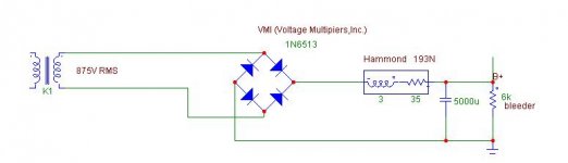
I don't know the regolation of your your supply
transformer. Hoever with a solid state bridge it
would give you more volts than with tube.
You can try this configuration, where
the 5000u cap has to be made using an
appropriate serie of greater caps paralleled
with resistances.
It will have about 0.05 Vrms of hum at B+, I think it is good.
I have use these VMI diodes
http://www.voltagemultipliers.com/spice models/spice_1n6513.pdf
and this choke
http://www.audiokit.it/ITAENG/Trasformatori/Hammond/Hammond_Chokes_(enclosed)_5c0033.pdf
Ciao
Attachments
schemes
Hi Federico,
The mercury rectifiers only drop ~10V at all current flows, so they should be OK in that respect. They don't like big capacitances though. Also, I am nervous enough about 700V supply, so I don't think I want to try the 1050V supply in the 3rd schematic. I do have a question of how much ripple is acceptable in the supply to the 845s?
Have you modeled the output of any of the configurations?
Thanks,
Michael
Michael
Yes, I have modelled the cir but now I have them
at home.
However the trafo model are not complete.
Standard fixed bias version gives me about
50 W with a swing to +50V at grid.
I dont know when ripple is acceptable because it
also depends on construction accuracy of
the opt trafo. You know, with perfect balanced
trafo any supply noise will cancel.
excuse my ignorance, I am impressed.
Yes, I have modelled the cir but now I have them
at home.
However the trafo model are not complete.
Standard fixed bias version gives me about
50 W with a swing to +50V at grid.
I dont know when ripple is acceptable because it
also depends on construction accuracy of
the opt trafo. You know, with perfect balanced
trafo any supply noise will cancel.
The mercury rectifiers only drop ~10V at all current flows
excuse my ignorance, I am impressed.
cathode or fixed bias
Hi Federico, All,
As I think I have mentioned I am not decided on whether to use fixed or cathode bias. I see some advantages to each method. Since I will be having it on the breadboard I thought I would probably try both ways and give it some listening and testing.
When you are biasing at -100V, is that set for AB operation? What is the idle current? What transformer impedance are you modeling, the 11.5k hookup?
The VMI diodes look good, does anyone know where to source them? I am planning a hybrid bridge with two 866s or 872s and two silicon diodes. Any tips?
Later,
Michael
Hi,
Aaaarrrggghhhh....Yeah, I mean DHT. What was I thinking.
Ciao,
what you mean with IDHT? 845 is a DHT (direct heated triode).
Aaaarrrggghhhh....Yeah, I mean DHT. What was I thinking.
Ciao,
filament current ramp
Thanks Federico.
A completely different question. Assuming it would be a good thing to have a slow current ramp up for the filaments at turn on and assuming AC filament supply, what is the best way to limit the turn on current? What is the simplest way?
I am putting together a sort of wish list of circuit features and then trying to pare it down to what is most necessary or most desirable so as to fit budget and space constraints. These things for the most part aren't part of the audio path, but parts for safety, tube life, etc. Such things as delay-relay for the HV primary (necessary for MV tubes), umbilical connection safety connection, bias supply failure shutdown relay. Anyone have suggestions for things to consider?
Thanks,
Michael
Hello Michael
library is here.
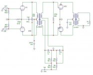
Here is my suggestion to fixed bias and static
balancing of the 845 currents.
As you see it use two 100k pot, thus
requiring about 2mA.
( as is the grids are at -85V)
I have some problem to conceive a dinamic
balancing method. Any suggestions?
Federico
P.S. Start thinking to the heater
library is here.
Here is my suggestion to fixed bias and static
balancing of the 845 currents.
As you see it use two 100k pot, thus
requiring about 2mA.
( as is the grids are at -85V)
I have some problem to conceive a dinamic
balancing method. Any suggestions?
Federico
P.S. Start thinking to the heater
Attachments
Hi Michael
what's the premium?
in the cir above, for instance, if you increaseb the
mu of one tube of 1% current change from
88.9mA to 85.7mA.
However, similar results can be obtained by varying
the ( I do not remember the name ) constant k in
the Child equation or changing the contact potential between
grid and cathode and so on.
However if the static currents are different then the curves
are different too. It can be only a traslation, or a gain difference
or a resistance difference. I do not know what picture is
usually true. Maybe a mix of all.
Federico
dynamic balance
Hi Federico,
What I was wondering about was dynamic balance by variable feedback. From this picture, if redrawn somewhat, the two R from the centertap of the interstage would be the 85k of the bias voltage divider. If one tube conducted less at DC then it's R would be made smaller, correct? Since that R is also the R across which feedback voltage is developed, less feedback would be applied to that tube and net gain would be increased. Any validity to the idea?
Michael
Attachments
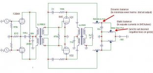
Compliments Michael
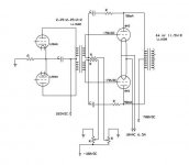
Your idea works well!
but I have changed something to separate
static from dinamic balance.
I have redrawn the cir as follows.
Dinamic balance succeded in cancel 2nd Harm
when I introduce some unbalance (for instance in the
output trafo)
the pot has to be limited to 500/1000 Ohm not to
introduce too much NF. This kind of NF decrease
the resistance seen by each tube.and this is not good.
So small pot. But it works well.
However I still looking for a more traditional method
( without NF).
Any suggestions from the gurus here.
Frank, any advice?
Federico
Attachments
cool
Hi Federico,
Glad the idea worked. Actually, you have redrawn the schematic exactly as I pictured it, but didn't have time to redraw myself yesterday. I am not morally opposed to feedback. I would like to try the circuit without added feedback, but if small amounts of local type were included for reasons of dynamic balance or other reasons, I think it could be OK. Only listening tells.
You said, "This kind of NF decrease
the resistance seen by each tube"
What resistance are you talking about here? The load on the 845 or the load on the 12B4? Or the resistance from grid to AC ground?
What primary impedance are you using for the LL1620 in your model?
Could you send me a .cir file for the model above?
Thanks,
Michael
fb
Federico,
When I say I am not opposed to feedback, I also understand that with the driver circuit I have designed there isn't a lot of headroom for feedback. I think without feedback the driver stage should just stay in the low distortion regime for output voltage to drive the 845 grid to ~+50V. It would not pay to work improvements on the output stage through feedback, if the driver performance markedly deteriorates.
Have you modelled the transistion to grid current yet? How does the driver stage react? The circuit as a whole? Would the feedback as you've drawn above have an effect on this aspect of the performance?
Also Federico, many thanks for the great efforts you have expended in helping to characterize these designs.
Thanks again,
Michael
- Status
- This old topic is closed. If you want to reopen this topic, contact a moderator using the "Report Post" button.
- Home
- Amplifiers
- Tubes / Valves
- 845 PP and Lundahl 1620