Hi Marcel,
Waiting for the parts to come, I played a bit with the 7th order analogue filter and would appreciate to get your opinion on what I tried below.
I examined the effect of removing the first filter, and changed the first op-amp for a LT1486 with almost 100Meg GBW, thereby turning the whole filter into a 6th order one, and because of that a few other components had to be changed as well to keep the FR and gain the same as before.
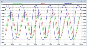
Knowing that you used the first filter with 3.3nF to prevent the first op-amp from overloading the input, the LT1486 still in the MFB setup that you used faces no problem at all, as shown in the first image below, where a 1V@27Mhz signal with rise and fall time of 0.5nsec were offered.
In Red you see the input signal at the minus input of the LT1486, in Blue the slew rate of this input signal, not exceeding 6mV/usec and finally in Green the op-amp's output signal.
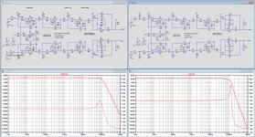
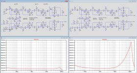
With this 6th order filter I compared resp. the FR + GD and the noise production, see second and third image below, with in each picture at the left the 6th order and at the right the original 7th order filter are shown, all on the same scale.
Hans
.
Waiting for the parts to come, I played a bit with the 7th order analogue filter and would appreciate to get your opinion on what I tried below.
I examined the effect of removing the first filter, and changed the first op-amp for a LT1486 with almost 100Meg GBW, thereby turning the whole filter into a 6th order one, and because of that a few other components had to be changed as well to keep the FR and gain the same as before.
Knowing that you used the first filter with 3.3nF to prevent the first op-amp from overloading the input, the LT1486 still in the MFB setup that you used faces no problem at all, as shown in the first image below, where a 1V@27Mhz signal with rise and fall time of 0.5nsec were offered.
In Red you see the input signal at the minus input of the LT1486, in Blue the slew rate of this input signal, not exceeding 6mV/usec and finally in Green the op-amp's output signal.
With this 6th order filter I compared resp. the FR + GD and the noise production, see second and third image below, with in each picture at the left the 6th order and at the right the original 7th order filter are shown, all on the same scale.
Hans
.
Attachments
Hi Hans, the digital part has a droop compensation built in, so for the flattest possible response, the analogue filter has to roll off a bit or the digital part has to be changed (FPGA code resynthesized with one different coefficient file). The digital droop correction filter has a magnitude response
1 + 13/256 - (19/512) cos(2 pi f T) - (7/512) cos(4 pi f T) with T = 5 us.
This is only a small correction: 1.009680428 or +0.083678759 dB at 15 kHz, 1.016534293 or +0.142440687 dB at 20 kHz, peak of about +0.644660534 dB at 73.5 kHz.
Apart from that, I don't see any problems with your alternative filter. You will get a bit less noise in band and a bit more ultrasonic quantization noise than I had.
A DSD-only version with only a raw DSD interface and no decimation, just like the Signalyst DSC1, would be much cheaper because it wouldn't need the FPGA module, nor the SRC4392 ASRC chip, nor the DIX4192 S/PDIF interface.
Is a DSD-only version worth revisiting Marcel? I could be tempted.
Could it utilise similar reconstruction filters to the ValveDAC?
Hi Marcel. I was thinking along the lines of the latter, passive, filter option - wondering if it might be possible to use some parts left over from the Valve DAC project?
I imagine a DSD-only version of this design would be significantly smaller and more affordable. I'm assuming a similar input arrangement to the DSD-only Valve DAC with HQPlayer upstream and a Beaglebone/Isolator/Reclocker on the input (an AK4137 based input would be nice but they're very scarce and pricey!)
Ray
OK, thanks Marcel - I should have thought it through more before asking the question 
Rational or not, I have an aversion to all those opamps on the output filter so perhaps the first clarification is the one to consider, "...an active filter, but redesigned for third-order Butterworth at 40 kHz...50 kHz...".
Maybe the output filter stage could be on a separate (stackable?) 2-layer PCB to enable experimentation, which would have the additional benefit of further constraining the size, and therefore cost, of the 4-layer DAC board?
Ray
I have some vague ideas for a new solid-state RTZ FIRDAC. If I ever work them out, I will probably start with something that could be used as a standalone DSD DAC. I don't know when and if that will happen, though.
Hi Ray,Maybe the output filter stage could be on a separate (stackable?) 2-layer PCB to enable experimentation, which would have the additional benefit of further constraining the size, and therefore cost, of the 4-layer DAC board?
Ray
Yes, a stackable filter would have been nice, so are other options that I would have preferred like XLR and coax sockets directly mountable on the PCB, but apart from that, Marcel did an incredable job with lots of attention to the smallest possible details in hard and software.
And you have enough options to change the output filter the way you like it on the current PCB.
I’m going for a 6th order filter with the more modern OPA1656, completely DC coupled, possibly gaining some additional S/N.
This already saves a lot on components like 8 expensive caps less and 8 much cheaper opamps.
Constraining the price of the PCB is a non issue.
I paid less then $10,- per PCB, so if you want one let me know.
Hans
- Home
- Source & Line
- Digital Line Level
- 74AHC02 and 74AHC08 DAC with 97 dB(A) dynamic range