I paid less then $10,- per PCB, so if you want one let me know.
Actually, thinking about it, why not!
It'll be a slow burn project with all that hand smd soldering and I imagine with the current global silicon supply problems some of the parts might be difficult to obtain in the short-term but it will be a good learning opportunity, experimenting with Marcel's settings options will be interesting and I can definitely make use of a PCM input DAC in my second system.
Can you share your output filter schematic, it sounds interesting.
I'll PM you about a PCB.
Ray
The FPGA modules are out of stock, as are many FPGAs and FPGA modules. The TE0630 LX75 module won't be available until well into 2022, but Trenz Electronic should have the cheaper TE0630 LX45 modules again this October.
As you know, there is a version 3 of the configuration file that works with the LX45. It has a better choice of quantizer sample rates, so the requirements on the stopband suppression of the interpolation chain could be relaxed, which made it fit in the LX45 module.
As you know, there is a version 3 of the configuration file that works with the LX45. It has a better choice of quantizer sample rates, so the requirements on the stopband suppression of the interpolation chain could be relaxed, which made it fit in the LX45 module.
Actually, thinking about it, why not!
It'll be a slow burn project with all that hand smd soldering and I imagine with the current global silicon supply problems some of the parts might be difficult to obtain in the short-term but it will be a good learning opportunity, experimenting with Marcel's settings options will be interesting and I can definitely make use of a PCM input DAC in my second system.
Can you share your output filter schematic, it sounds interesting.
I'll PM you about a PCB.
Ray
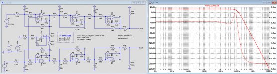
Here is the output filter that I have planned to use.
Four OPA2134 being replaced by three OPA1656 because of using DC coupling, making the last opamp acting as a buffer obsolete.
The servo remained the OPA134.
All 220nF 5%, 100nF 5%, 2,2uF audio grade and 3n3 2% are removed.
The 10nF 2% being replaced by 1nF 2%.
Hans
.
Attachments
I have some vague ideas for a new solid-state RTZ FIRDAC. If I ever work them out, I will probably start with something that could be used as a standalone DSD DAC. I don't know when and if that will happen, though.
+1 on "interest list" should it materialize someday
")
Cheers,
Jesper
I received a PCB for this project courtesy of Hans. Whilst it's much smaller than the Valve DAC board it is going to be much more of a challenge to assemble because of the large amount of smd soldering, some of which is very fine. I'm not holding my breathe for a quick project - I think this will be one for a patient 'bite at a time' approach, though to some extent I anticipate availability of parts will force that anyway.
The two connectors for the FPGA module are the most difficult parts to solder, then the two ICs in TQFP-48 packages. Everything else is easy compared to that.
Yep, those connectors look daunting but at least they're not active parts so may tolerate any necessary rework better, though the bads will be easy to overheat and delaminate!
Hi Marcel, this is probably showcasing my naivity/ignorance but I'll ask anyway - is it possible to bypass the FPGA and associated sections and input the SDM (DSD) data/clock signals from something like a JLSounds board into the Delta-Sigma cores of this DAC? I'm assuming that your input sections based around the FPGA output deliver similar SDM data/clock signals at some point?
http://jlsounds.com/uploads/I2SoverUSB v.III.pdf
http://jlsounds.com/uploads/I2SoverUSB v.III.pdf
I did in fact think about how to make a DSD version a long time ago, see the attachments. I'm not sure if you can get this onto the existing PCB somehow. I never tried this circuit, so use it at your own risk.
U20 has turned into a different logic family and is connected straight to U18A and U18B (U21 is gone).
The left and right data and bitclock are connected to U11 and the bitclock also to the new U20.
U19 is new, so you would need to put it on a perfboard or so with a decoupling cap.
I've drawn a +5Vraw that's derived from the LT3042, but that's not necessary.
I'm not sure the mute will be fast enough.
See post #122 about the termination resistors (also for the PCM version).
Attachments
I suspect that will be inevitable Marcel.
I haven't even thought about making a start on this project using the board I got from Hans because I'm have difficulty getting parts for current projects and I keep getting messages that parts I already have on back order are being further delayed...
I haven't even thought about making a start on this project using the board I got from Hans because I'm have difficulty getting parts for current projects and I keep getting messages that parts I already have on back order are being further delayed...
Guys, just putting it out there that if you really want to get this project going that I have a spare LX75 FPGA. Am happy to send it on to someone doing one of Marcels projects for what is has cost me. Was purchased on a whim because it was there (at Mouser) and they have been so difficult to source.
I just noticed a silly mistake that I overlooked before: the decoupling capacitors for the op-amps are specified to be 25 V types, but the ones between the positive and the negative supply rail actually have 30 V across them. Considering the non-linearity of X5R capacitors, they have to have at least 50 V nominal working voltage. Apologies for the inconvenience!
- Home
- Source & Line
- Digital Line Level
- 74AHC02 and 74AHC08 DAC with 97 dB(A) dynamic range