I can understand the insensitivity to duty cycle, but the rest makes no sense at all. Take a pencil and a piece of paper, draw the waveforms and you can show to yourself that when the positive and negative sides don't match, the version with only flip-flops and resistors has to be sensitive to differences between rising and falling flip-flop delays and that it depends on the pattern how big the impact is.
Yes of course does delay have it's impact on the Resistor Only version.
But you have take into account also that those differences are compensated by the spikes in between, the same what happens with the gated versions, but for them to a lesser degree.
See the waveforms for 01010 and 01100 with the aggressive delay.
That's not something you can easily draw with pen and paper.
Hans
.
Attachments
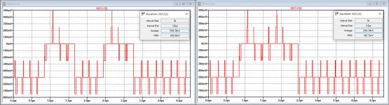
Compare those relatively "acceptable" waveforms for the Resistor Only version in the above posting to those produced by the 2*4 gated version with the aggressive delay scheme.
Their average values between 01010 and 01100 are still close, but with much more glitches in the signal.
Hans
.
Their average values between 01010 and 01100 are still close, but with much more glitches in the signal.
Hans
.
Attachments
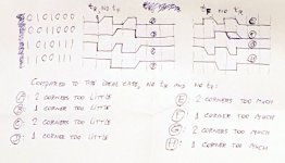
Attached are sketches of the eight basic waveforms for the non-return-to-zero case (resistor only case, as you call it). These are single-ended waveforms at a flip-flop output for the two bit patterns and their inverses. For clatity, I've chosen zero propagation delay and either a nonzero rise or a nonzero fall time.
The differential output voltage of the differential two-tap FIRDAC is a linear combination of waveforms like this:
For a 0101000 pattern: half an A or E plus half a delayed A or E minus half a C or G minus half a delayed C or G
For a 0011000 pattern: half a B or F plus half a delayed B or F minus half a D or H minus half a delayed D or H
Hence, the error is also a linear combination of the errors on these waveforms. For example, when the positive and the negative outputs have a rise and no fall time:
010100: 2/2 corners too little + 2/2 corners too little - 2/2 corners toi little -2/2 corners too little = 0 error
0011000: 1/2 corner too little + 1/2 corner too little - 1/2 corner too little - 1/2 corner too little = 0 error
Clearly, when the corners are different in size, they will in general not cancel perfectly and to what extent they do cancel may become pattern-dependent.
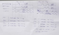
An extreme (though somewhat unrealistic) example is when the positive sides have a rise time and the negative a fall time:
0101000: 2/2 corners too little + 2/2 corners too little - 2/2 corners too much - 2/2 corners too much = 4 corners too little
0011000: 1/2 corner too little + 1/2 corner too little - 1/2 corner too much - 1/2 corner too much = 2 corners too little
In reality there will be some, but no perfect matching between the positive and negative sides, so you should get some pattern-dependent error.
The differential output voltage of the differential two-tap FIRDAC is a linear combination of waveforms like this:
For a 0101000 pattern: half an A or E plus half a delayed A or E minus half a C or G minus half a delayed C or G
For a 0011000 pattern: half a B or F plus half a delayed B or F minus half a D or H minus half a delayed D or H
Hence, the error is also a linear combination of the errors on these waveforms. For example, when the positive and the negative outputs have a rise and no fall time:
010100: 2/2 corners too little + 2/2 corners too little - 2/2 corners toi little -2/2 corners too little = 0 error
0011000: 1/2 corner too little + 1/2 corner too little - 1/2 corner too little - 1/2 corner too little = 0 error
Clearly, when the corners are different in size, they will in general not cancel perfectly and to what extent they do cancel may become pattern-dependent.
An extreme (though somewhat unrealistic) example is when the positive sides have a rise time and the negative a fall time:
0101000: 2/2 corners too little + 2/2 corners too little - 2/2 corners too much - 2/2 corners too much = 4 corners too little
0011000: 1/2 corner too little + 1/2 corner too little - 1/2 corner too much - 1/2 corner too much = 2 corners too little
In reality there will be some, but no perfect matching between the positive and negative sides, so you should get some pattern-dependent error.
Attachments
Marcel,
In your drawings it seems that you assume that only the summing points of the four gates have to do with rise and fall time.
Fact is that each individual gate has it's own rise and fall time.
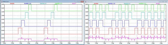
See first image below at the left how the four individual outputs are creating the positive output in lilac, and at the right the same for the inversed output in lilac composed from the four individual signals.
The second image then shows the differential signal from the two lilac signals, the one also shown in posting #83.
Hans
.
In your drawings it seems that you assume that only the summing points of the four gates have to do with rise and fall time.
Fact is that each individual gate has it's own rise and fall time.
See first image below at the left how the four individual outputs are creating the positive output in lilac, and at the right the same for the inversed output in lilac composed from the four individual signals.
The second image then shows the differential signal from the two lilac signals, the one also shown in posting #83.
Hans
.
Attachments
Hans, my drawings are for 1 flip-flop output (post #84) or 1 gate output (post #86).
In post #84, I (qualitatively) derive the best-case and worst-case pattern-dependence of the error of the average FIRDAC output voltage from the pattern-dependence of the average output voltage of each flip-flop. In post #86, there is no pattern-dependence of the average output voltage of each gate, so there won't be any at the FIRDAC output either. To find the average FIRDAC output voltages, there is no need to draw the FIRDAC output waveform, just to know that it's a linear combination of flip-flop or gate output voltages.
In post #84, I (qualitatively) derive the best-case and worst-case pattern-dependence of the error of the average FIRDAC output voltage from the pattern-dependence of the average output voltage of each flip-flop. In post #86, there is no pattern-dependence of the average output voltage of each gate, so there won't be any at the FIRDAC output either. To find the average FIRDAC output voltages, there is no need to draw the FIRDAC output waveform, just to know that it's a linear combination of flip-flop or gate output voltages.
Sorry, but I’m lost in what you are telling and drawing for just 1 FF or 1 Gate.
What exactly is your conclusion in comparing the complete differential 4 gated version versus the differential resistor only version in this 2 stage FIR Dac ?
Do you agree that for both versions only the output level is affected by rise and fall times, but that 01100 and 01010 patterns give equal output independent of rise and fall times as shown in posting #78 ?
And when you don’t agree, why is that ?
Hans
Sorry, but I’m lost in what you are telling and drawing for just 1 FF or 1 Gate.
What exactly is your conclusion in comparing the complete differential 4 gated version versus the differential resistor only version in this 2 stage FIR Dac ?
The average output voltage of any of the gated versions should just depend on the percentage of ones and not on the exact pattern (011000 versus 010100), but that should not be the case for the version consisting of only flip-flops and resistors. There are exceptions, for example when the delays of the positive side are all equal to those of the negative side, but the probability of ending up in such a case by chance is 0.
Do you agree that for both versions only the output level is affected by rise and fall times, but that 01100 and 01010 patterns give equal output independent of rise and fall times as shown in posting #78 ?
No, I don't believe the results you get for the flip-flops and resistors variant.
And when you don’t agree, why is that ?
That's what I tried to explain in post #84. When you look at each flip-flop output separately, you will see that when rise and fall times or rising and falling delays are unequal, 011000 does not exactly give the same average as 010100. Taking an extreme example for simplicity: when you have no rise time (or rising delay) but a fall time (or falling delay), 010100 will have a larger average than 011000, because the voltage has to fall twice in 010100 and only once in 011000. It's the opposite when you have a rise time and no fall time. When you have both, it's the difference that matters.
The output signal of an N-tap FIRDAC made of flip-flops and resistors is a linear combination of signals at flip-flop outputs, so its average output voltage is a linear combination of average flip-flop output voltages.
Each and every flip-flop output has its own rising and falling delays, so it would be a remarkable coincidence if the pattern-dependent errors they cause would cancel exactly. They can cancel partly, and in fact it's very likely that they do, but exactly is weird. I therefore don't trust your simulation.
To debug the simulation or my line of reasoning or both, for the case with only flip-flops and resistors and with delays, for each of the two bit patterns, could you list the average flip-flop output voltages (between Q and ground and between Qnot and ground) and the average differential FIRDAC output voltage?
The average output voltage of any of the gated versions should just depend on the percentage of ones and not on the exact pattern (011000 versus 010100), but that should not be the case for the version consisting of only flip-flops and resistors. There are exceptions, for example when the delays of the positive side are all equal to those of the negative side, but the probability of ending up in such a case by chance is 0.
No, I don't believe the results you get for the flip-flops and resistors variant.
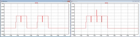
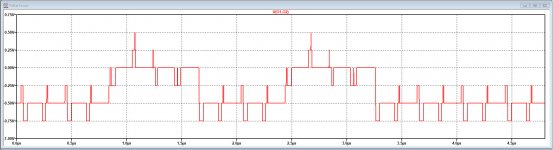
You are hard to convince, that's why I show all relevant details in one image.
You see for 01100 and 01010 both the delayed and the non-delayed version in one plot, resp. as V(PD,ND) and V(P,N).
The non delayed versions have both 666.67mV as average value and the aggressive delayed versions have both 669.17mV average value.
Further I have included the LTSpice .asc files plus delay subfiles in one Zip file for you to check.
Either I'm doing something wrong, LTSpice has become mad or you are wrong in your assumptions.
Hans
.
Attachments
Hi Hans,
You were comparing two bit patterns that each had at least one zero between the ones, namely 010001000000 versus 010100000000. When you change V2 in either one of your schematics into PULSE(0 1 700n 1n 1n 800n), you get two consecutive ones and you'll see what I mean.
Best regards,
Marcel
You were comparing two bit patterns that each had at least one zero between the ones, namely 010001000000 versus 010100000000. When you change V2 in either one of your schematics into PULSE(0 1 700n 1n 1n 800n), you get two consecutive ones and you'll see what I mean.
Best regards,
Marcel
Hi Marcel,
I'm sorry, but I don't get what you mean.
Pulse(0 1 700n 1n 1n 800n) is not a complete instruction, it still misses the period and the number of cycles.
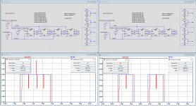
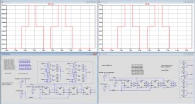
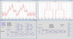
When I take 1600n as the cycle time and 2 cycles, I get the images below from the 4 gated version and from the resistor only version.
The left image without delay for an uncluttered image, but both exactly the same and the second image with included delay.
But isn't the critical Fir Dac issue for what comes out and not the incoming single bit stream that's synchronised by the clock and not sensitive to any rise and/or fall times.
Hans
.
I'm sorry, but I don't get what you mean.
Pulse(0 1 700n 1n 1n 800n) is not a complete instruction, it still misses the period and the number of cycles.
When I take 1600n as the cycle time and 2 cycles, I get the images below from the 4 gated version and from the resistor only version.
The left image without delay for an uncluttered image, but both exactly the same and the second image with included delay.
But isn't the critical Fir Dac issue for what comes out and not the incoming single bit stream that's synchronised by the clock and not sensitive to any rise and/or fall times.
Hans
.
Attachments
The default period time is infinite, so PULSE(0 1 700n 1n 1n 800n) just gives you one pulse of 800 ns wide, that is, two consecutive ones when the clock period is 400 ns.
Besides, please have a look at the individual flip-flop and gate outputs, not only the FIRDAC outputs that are linear combinations of flip-flop or gate outputs anyway. It is much easier to see what's going on when you (also) look at individual gates and flip-flops.
What matters is that the average output voltage depends on the percentage of ones and not on the precise pattern. Any circuit I know of will have no problem with 010001000000 versus 010100000000, but 011000000000 is a whole different cup of tea because the flip-flop-resistor version will have two transitions less than on the 010001000000 and 010100000000 patterns.
Last edited:
Hi Marcel,
At last, there we are.
It took a while, but you are right with the patterns now suggested.
So it is not the skewing of the 01010 and 01100 rise and fall times from the SDM, but the effect different patterns have on the gated Fir Dac output were the gates are having different rise and fall times.
That's what confused me.
But I'm with you that the gated RTZ version is superior to the resistor only version, case closed.
So now comes the next step in building the thing.
You mentioned to have a version with a 4 stage Fir Dac.
Are there Gerbers available for this version also ?
Hans
Hi Hans,
Glad that we got that cleared up!
Regarding four-tap RTZ FIRDACs: what I meant to say is that the circuit of posts #1 and #23 is in fact a four-tap RTZ FIRDAC. It's RTZ in the sense that each and every stage returns to zero, but as they are time-interleaved with half cycle delays, the output of the entire FIRDAC does not return to zero (except maybe during switching spikes). Nor does it have to, as far as I'm concerned.
As a reminder, a simple FIRDAC made of flip-flops and resistors could work very well when the embedded pulse width modulator in the sigma-delta modulator is changed such that you always get one rising and one falling edge per PWM pattern. For example, for PWM9, you could kick out the random rotation and avoid codes 0 and 9, so you only have patterns 000000001, 000000011, 000000111, 000001111, 000011111, 000111111, 001111111, 011111111. It would be nicer to centre those patterns, like 000010000, 000110000, 000111000, 001111000, 001111100, 011111100, 011111110, 111111110. This will result in a small amount of distortion, but that is still suppressed by the entire sigma-delta loop (as long as the loop filter runs on the 27 MHz PWM bit clock, which it does). What I haven't thought about yet is the pattern-sensitivity of the current out of the reference with such a DAC.
Best regards,
Marcel
Last edited:
Marcel,
You have used two different FFPA modules.
When I want the best posible sound reproduction, does the more expensive version has longer/more sophisticated Fir filters ?
After all we have seen in the NOS/OS Dac thread the importance of high quality Fir filters used while upsampling.
Hans
You have used two different FFPA modules.
When I want the best posible sound reproduction, does the more expensive version has longer/more sophisticated Fir filters ?
After all we have seen in the NOS/OS Dac thread the importance of high quality Fir filters used while upsampling.
Hans
- Home
- Source & Line
- Digital Line Level
- 74AHC02 and 74AHC08 DAC with 97 dB(A) dynamic range