Emitter resistors are necessary in the real world as they help in current sharing between paralleled transistors - remember real parts are not perfectly equal in their parameters (especially beta or VGS) ") This is one of the points not seen in simulation.
This is one of the points not seen in simulation.
Another point is that simulation regularly predicts unrealistic results. That's due to insufficient models and often also due to incorrect simulation. Just simulate a known amp (where you have all specs and plots) and compare. You will be surprised.
In any case, at these low levels of THD also construction details as pcb-layout, wiring, position of the toroid and more become decisive wether you reach your goal or not.
Do not keep your eye so close to the simulator, build and measure the beast.
Have fun, Hannes
PS: if you want real fun, measure THD while moving the wiring in the amp.
This is one of the points not seen in simulation.Another point is that simulation regularly predicts unrealistic results. That's due to insufficient models and often also due to incorrect simulation. Just simulate a known amp (where you have all specs and plots) and compare. You will be surprised.
In any case, at these low levels of THD also construction details as pcb-layout, wiring, position of the toroid and more become decisive wether you reach your goal or not.
Do not keep your eye so close to the simulator, build and measure the beast.
Have fun, Hannes
PS: if you want real fun, measure THD while moving the wiring in the amp.
Fotios, I never thanked you properly for your help on the transformers. Thanks, Fotios.
Well, I got some small heatsinks out of the monitor and will breadboard a small prototype in a minute with no parallel outputs. Let's hope the smoke stays inside.
- keantoken
h_a said:Emitter resistors are necessary in the real world as they help in current sharing between paralleled transistors - remember real parts are not perfectly equal in their parameters (especially beta or VGS)
Another point is that simulation regularly predicts unrealistic results. That's due to insufficient models and often also due to incorrect simulation. Just simulate a known amp (where you have all specs and plots) and compare. You will be surprised.
In any case, at these low levels of THD also construction details as pcb-layout, wiring, position of the toroid and more become decisive wether you reach your goal or not.
Do not keep your eye so close to the simulator, build and measure the beast.
Have fun, Hannes
PS: if you want real fun, measure THD while moving the wiring in the amp.
Well, I got some small heatsinks out of the monitor and will breadboard a small prototype in a minute with no parallel outputs. Let's hope the smoke stays inside.
- keantoken
keantoken said:
There isn't a metal pad on the back. Just plastic.
Most TO-126 are like this. In my opinion, a benefit - no isolation washer needed, just grease it up an' bolt it on.
By MJL - There isn't a metal pad on the back. Just plastic
That is strange.. old 340's and even old c3503's HAVE metal
on the backs of the devices, but the new MJE/KSA to-126's
are all plastic.
Once I found this out I realized you could mount them
"backwards" for PCB layouts,etc . No mica required either
.OS
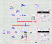
I am struggling with this Single End MOSFET Class A.
It is kinda ZEN but uses one current source at 1 Ampere.
Output devices are N-Channel.
Only four transistors: 2 x 2N5401 and 2 x Exicon ECF20N20
Think two Exicon ECF10N20 will work just as well.
At 18 VDC, 1 Ampere = 18 Watt,
it can produce 2, maybe 2.5 Watt RMS with acceptable dist.
Mainly 2nd and 3rd harmonics. The higher orders will fall off nicely.
It is not easy to balance gain, bias and operation voltage
to make this amplifier optimal.
But it is a nice project and fairly low idle powers.
Lineup
It is kinda ZEN but uses one current source at 1 Ampere.
Output devices are N-Channel.
Only four transistors: 2 x 2N5401 and 2 x Exicon ECF20N20
Think two Exicon ECF10N20 will work just as well.
At 18 VDC, 1 Ampere = 18 Watt,
it can produce 2, maybe 2.5 Watt RMS with acceptable dist.
Mainly 2nd and 3rd harmonics. The higher orders will fall off nicely.
It is not
easy to balance gain, bias and operation voltageto make this amplifier optimal.
But it is a nice project and fairly low idle powers.
Lineup
Attachments
Hi Lumba,
not that I'm aware of
Especially my last post was plain general info that everybody also finds with a little search here on the forum.
But I think you just refer to my putting down of SPICE; I think you maybe misunderstand me here. SPICE is a perfectly nice tool for evaluating amps, but it has it's limits. If you seriously go for anything less than 0.05% THD I would not trust SPICE. The models are - in my experience - much too limited in quality.*
Of course one can improve them (andy_c did that), but everybody who is able to do that also knows the above.
Have fun, Hannes
*real pros excluded.
lineup said:I am struggling with this Single End MOSFET Class A.
It is kinda ZEN but uses one current source at 1 Ampere.
Output devices are N-Channel.
Only four transistors: 2 x 2N5401 and 2 x Exicon ECF20N20
Think two Exicon ECF10N20 will work just as well.
At 18 VDC, 1 Ampere = 18 Watt,
it can produce 2, maybe 2.5 Watt RMS with acceptable dist.
Mainly 2nd and 3rd harmonics. The higher orders will fall off nicely.
It is not
to make this amplifier optimal.
But it is a nice project and fairly low idle powers.
Lineup
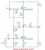
Interesting circuit. I've never messed with MOSFETs. It looks like the current mirror could easily be turned into a push-pull configuration a la Doug Self.
An externally hosted image should be here but it was not working when we last tested it.
EDIT: OMFG... The image is larger than I thought...
- keantoken
lineup said:
It is not
to make this amplifier optimal.
But it is a nice project and fairly low idle powers.
Lineup
Play with this idea.
Nico
Attachments
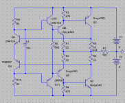
Okay, I finally have the output stage working. Didn't have much time to work on it, but he output stage is working now.
Attached file is the components I used.
The circuit oscillates if I attach anything between the emitter of Q3 and Q4.
I will go ahead and build the input and feedback parts of the circuit to see if I can get it so I can listen to it.
- keantoken
Attached file is the components I used.
The circuit oscillates if I attach anything between the emitter of Q3 and Q4.
I will go ahead and build the input and feedback parts of the circuit to see if I can get it so I can listen to it.
- keantoken
keantoken said:
Interesting circuit. I've never messed with MOSFETs. It looks like the current mirror could easily be turned into a push-pull configuration a la Doug Self.
http://www.dself.dsl.pipex.com/ampins/discrete/cfp3.gif
- keantoken
I know about that circuit from D.Self site.
It is something between one CCS loaded output stage and Push-Pull.
It is a possible way to increase the power output.
However, I think it will make less PSRR.
CCS has got very good power supply rejection ratio. This is why I prefer this.
Nico Ras circuit looks very good.
But same here. The PSRR will suffer a bit
Regards
http://www.diyaudio.com/forums/attachment.php?postid=1731211&stamp=1233473601keantoken said:Here's file.
- keantoken
That output stage is something to explore further.
I must say you are good, keantoken
I love members that have the ability to think Out of The Box
And you are certainly a creative person, mate.
Like Nico Ras, too ....
Lineup Regards
Here at my place it is 9 in the morning, Sunday Morning
Johnny Cash - Sunday Morning Coming Down
Johnny Cash - Sunday Morning Coming Down
On a Sunday morning sidewalk,
I'm wishing, Lord, that I was stoned.
'Cause there's something in a Sunday
That makes a body feel alone.
Q5 & Q6 are operating Iq~1.3mA that seems very low for 340/350 transistors.
I do believe that the two bias controlling transistors cannot work. I reckon that as soon as an emitter current changes, the transistor pair send corrections to the outputs and that your oscillation.
I do believe that the two bias controlling transistors cannot work. I reckon that as soon as an emitter current changes, the transistor pair send corrections to the outputs and that your oscillation.
- Status
- This old topic is closed. If you want to reopen this topic, contact a moderator using the "Report Post" button.
- Home
- Amplifiers
- Solid State
- 6W, Class A, hopefully something I can build. :D