The 10n cap is there to prevent oscillations. Yes, the bias pair is a very fast arrangement. If we make it higher than 100n, we usually get oscillations. if you want oscillations, however, try putting a cap between the bases of Q3 and Q4, or across R8.
In the simulator it works well, and gives low distortion if I attach a signal source between the emitters of Q3 and Q4. In real life I'm not sure. However, my breadboard work is a tangle of wires, so maybe I could stabilize the circuit by getting rid of some parasitics.
- keantoken
In the simulator it works well, and gives low distortion if I attach a signal source between the emitters of Q3 and Q4. In real life I'm not sure. However, my breadboard work is a tangle of wires, so maybe I could stabilize the circuit by getting rid of some parasitics.
- keantoken
I don't have any better output devices. I have to work with what I have. No money to order new devices.
But I want to do the best with what I have. While you have the impression I've been fibbling around, I've been trying to decide how I will do the input. PNP LTP, single or CFP VAS, etc.
There are so many different possibilities, and most of them probably give the same performance. Maybe I am wasting my time on the sim.")
This is the circuit intend to build now. I have no good speakers or headphones to test this on but here it goes.
And no complaints from the quality department!
- keantoken
But I want to do the best with what I have. While you have the impression I've been fibbling around, I've been trying to decide how I will do the input. PNP LTP, single or CFP VAS, etc.
There are so many different possibilities, and most of them probably give the same performance. Maybe I am wasting my time on the sim.
This is the circuit intend to build now. I have no good speakers or headphones to test this on but here it goes.
And no complaints from the quality department!
- keantoken
Attachments
It's aliiiiiiiiiive!
Later I will post pictures.
Can't judge sound quality because I'm having to listen on a 1-inch plastic transducer I got from inside a telephone about 5 years ago...
It's got issues. I may have just not put it together right.
Anyways, after I get it working better, I will attach more MJE's and attach it to a speaker...
- keantoken
Alright, the amp is stable.
I'm running two parallel MJe's, 150mA each, which is enough to drive a 16 ohm speaker at low volume.
I put the hollow base of a trophy on top of the speaker which almost serves as a good enclosure.
Currently the sound is crystal clear with no pops or ticks but I suspect some distortion. The treble is much better than my current system, I know this.
I will have to do some experimenting with the input LTP to see what I can do.
- keantoken
After extended listening on unfamiliar speakers and an inferior enclosure, I conclude that this amplifier sounds quite good.
The heatsinks are warm, but not unealthily so.
The box adds an interesting character to the sound, I've noticed. Although it sounds as if the music is being played inside a box, it adds an interesting woody sound to voice and gives guitar sounds character. I'll bet it would give a nice cabinet sound to some piano piece.
I'm still afraid to hook it up to my soundcard though. I'll add a diode limiter.
- keantoken
lineup said:Hi.
Are you using the circuit in post #43.
With +-6V
Yes, I am about to change that!
I couldn't figure out why my circuit was clipping. Now I know why. The CCS on the output stage won't deliver its current on strong negative peaks and the only solution to this is more voltage. Now it will run on +-12V.
So I should get enough amplitude to fry those little MJE's.
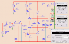
Here is the current version I am working with. We have graduated to a CFP VAS.
- keantoken
Attachments
I setup your 6 Watt Class A using:
- BC560C, BC550C
- BCP53-16, BCP56-16 .... new SMD variants of BD139/140
- MJE15030/31 ... fast 50 Watt TO-220 power transistors
Comp. cap C5 needs to be 470pF to stabilize.
This gives an upper bandwidth of ~1 MHz at gain 10.
With the addition of C2 (100pF) at the input the rolloff is at ~550 kHz.
At 6 Watt Class A output the THD is 0.003.
Very good
Attachments
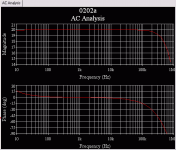
lineup said:Here you have AC analysis.
After adding C5 470pF and C2 100pF.
The rolloff is at 550 kHz and -45 degrees at 300 kHz.
Haven't done the FFT fourier yet.
I have not examined the C3, 10 nF. What value this cap needs to have?
C3 IS needed to keep the bias transistors from oscillating. The cap I'm using on the breadboard is a Wilma FKP 1, 6.2pF. Rated for 1.6Kv!
I realize the need for emitter resistance on the output devices but I don't have those kind of resistors. Currently I am without them.
Thank you for your interest, Lineup.
- keantoken
keantoken said:Thank you for your interest, Lineup.
- keantoken
Your amplifier idea is basically very good.
If you look at my schematic, I use 0.82 Ohm to set the output bias to ~0.8 Ampere (peak out = 1,6 A)
It may be enough with using 1 Ohm here, for 0.65 A = peak 1.3 A output.
Depends on the impdance curve of your 8 Ohm speakers
and your needed peak output power.
The circuit is working very well right now! It gets loud enough, I just need some decent speakers.
Next I need to get good heatsinks and attach all the MJE's.
After this it will be loud enough for me and I will then turn to decrease distortion.
Lineup, you are true friend.
Thank you,
- keantoken
Next I need to get good heatsinks and attach all the MJE's.
After this it will be loud enough for me and I will then turn to decrease distortion.
Lineup, you are true friend.
Thank you,
- keantoken
I once built one Class A that 'only' delivered 4-5 Watt.
I loved the sound of it.
For many cases this can be quite enough power.
People do not think so. But this is a fact.
We do not have many such lower Wattage Class A project.
So this one is welcome.
The idea is somewhat in line with Nelson Pass www.firstwatt.com
Using speakers with higher/medium sensitivity (Lowther), in order to be able to use less voltage/current gain.
A bit to the minimalistic audio way.
Builders is a rarity..we have thousands of speakers, talkers.... brainstorm folks
simulator addicted, theorics, brain orgasmic folks that loves schematics,narcisists, selfish folks, egocentric, squizofrenic, reviewers... review maniacs, people that intend to be a reviewer, paranoids,living calculators, counsellors, hiper boring folks,critics, teachers, masters, walking enciclopedias, walking parrots, people to comment, to contribute, to suggest, to give a better idea..to re design your schematic, to correct your errors, to give you advises and advices..big engineers, superb enginneers, the best enginneers (hundreds thinks about themselves as the best ones..ahahahah!)....but builder is a rarity.
You see..... a lot to talk..no one to build!
You're searching exactly what we have very few.... also people does not know english...forum is DO it yourself.... To do is the verb...means action!...people do nothing!
Forum has more than 70000 folks off topic.... around the forum doing nothing...real builders not more than 100 folks.... i calculate, from those 100 folks...around 70 folks are not more visiting the forum...maybe busy doing things.
Count the folks that had build something into the permanent pictures thread..... "post your pictures here"... and you gonna see what i mean..
Wanna see something built?.... move!
regards,
Carlos
...............................................................................................
Also you have gênius..alike Jacco Vermeulen... crazy folks that build things upside down and perfect moderators as Carl Weldon
Attachments
What amplifier Lineup?..... i do not know those ones.
I have a filter....mine own filter..personal filter... something i use to decide if i will read or not....when i see complicated schematics filled with CCS, mirrors, sinks and all stuff i use to jump out from the thread.... i use to search really new ideas, not those ones that uses "all modern resouces" trying to make something with very low THD or IMD.
Also i dislike class A and Field Effects (because hard to find here)... so...if Keantoken use this... really i have jumped out from the thread having only visited once to discover what was going on there.
Gimme a link and i will comment what i think directly to you using forum e mail adress.
regards,
Carlos
Keantoken,
The bias scheme for your output stage has first published by a W. Allison in Wireless World in Dember 1972 (which is worth reading if you can find it). I have spend the last 12 months or so carefully analysing this circuit for a variety of possible uses. I don't understand why it is rarely used, as it appears to be very good.
However I have found that having multiple devices between the bias controlling transistors and the output can result in some instability (especially with square waves).
I have attached (I hope this works) a design that I was working on last year (but never buit) for a good unity gain buffer, which turned out to much better that typical diamond buffers. Note the placement of the high frequency compensation capacitor (22pF) and the base resistor (1k). In this circuit I chose to drive it between the emitters of the bias control transistors (which gives the lowest distortion), however it can be current driven, which is how you (and the original Allison circuit) drive it. I also found that Mosfets gave better results than darlington transistors (though this could just be due to Spice model quality or lack of).
Consider doing the following:
1- Use my Allison compensation scheme,
2- Reducing the number of devices in the Allison feedback loop, such as just a simple darlington or Mosfet (irf610 would be good),
Note that the value of the resistors to bias control transistors (1k R4, R5 in the attachment). If voltage driven via the emitters then these resistors need to be in the range 500 to 10k. Large values allow the circuit to go into Class B operation. If current driven then the resistors need to be low (zero to 1k) - low values give current limiting, high values allow Class B operation.
I hope this is of help.
When I have some time to prepare the numerous diagrams, I'll publish the numerous ways that this bias scheme can be used. Using it as a driver for an output stage shows great promise!
Paul Bysouth Feb, 2009.
Attachments
- Status
- This old topic is closed. If you want to reopen this topic, contact a moderator using the "Report Post" button.
- Home
- Amplifiers
- Solid State
- 6W, Class A, hopefully something I can build. :D