John Broskie is very careful to say that the first stage of the Aikido does not operate Push Pull. The difference comes from the output connection is at the plate of the bottom triode not the cathode of the top triode as in the SRPP. This is similar to the question of is a mu-Follower still a mu-Follower with the optional output taken at the plate of the bottom triode?
The SRPP can source up to twice the current at lower output impedance.
The input stage of the Aikido is not unique to the Aikido it is circa WWII. The top triode was used to offset variable circuit performance due to changing heater voltage. Half the B+ voltage is dropped across the top tube and cathode resistor. The circuit performance and math works out such that the top triode operates as a resistor. The heater voltage varies plus or minus the equal B+ voltage split between both triodes is maintained. Also out of the math in the musty old books the rp’s of both top and bottom triodes being equal cancel out. Variable rp is no longer a player in producing distortion. This is much like parameter restriction with a CCS or is cancellation in the mathematical sense. The top tube is an active resistor.
One thing I have not digested or done the math on; is the noise of the top tube the same as, more than or less than the equivalent resistor if it was used in its place. Equivalent resistor Rp := 12500 with 6DJ8, B+ :=250V, Rk:=270R ma := 10.
For the PSRR with an Aikido I like to use a series regulator. <edit>
For Fun
DT
Last edited:
Noise current generated by the upper tube is a good deal worse than for a simple resistor.One thing I have not digested or done the math on; is the noise of the top tube the same as, more than or less than the equivalent resistor if it was used in its place.
I thought the point of Aikido was the converse of PSRR: the balanced currents (but only in the absence of a load) mean the PSU does not see any signal. This does not necessarily guarantee good PSRR, but it does give good inter-stage isolation.ruffrecords said:I thought the point of Aikido was its PSRR?
Yes, but if the lower cathode is bypassed this does not matter too much as the lower anode has lower impedance so partially shorts out noise from the upper valve. It could be a small problem (3dB) if no bypass is used.Merlinb said:Noise current generated by the upper tube is a good deal worse than for a simple resistor.
I think you're thinking of a CCDA arrangement (which can be combined with Aikido of course).I thought the point of Aikido was the converse of PSRR: the balanced currents (but only in the absence of a load) mean the PSU does not see any signal.
Strictly, Aikido is the name Broskie uses for the old trick of getting PSU noise to cancel itself out by injecting it somewhere else. But the topology of a half-mu feeding an active-loaded cathode follower is also informally called an Aikido, around here.
Last edited:
Noise current generated by the upper tube is a good deal worse than for a simple resistor.
To avoid me doing the calculator strokes myself and getting the grief for errors. I am referring to Morgan Jones valve Amplifiers 3rd edition page 533. r equivalent ~ 2.5/gm for a triode. The gm near the operating point of the 6DJ8 we are speaking of is ~5.3mA/V the equivalent resistance looks to calculate near 470R, a good bit less than the simple resistor model of near 12K.
For thermal noise it looks like the tube has the advantage.
DT
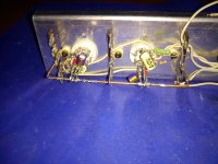
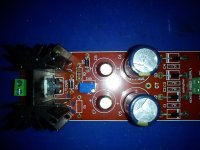
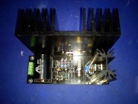
Started 1st proto with Mu-Follower due to the fact is more easy to make, the heaters of two valves in paralel with 6.3V? how much current draws to calculate the dummy load for the Salas HV shunt regulator? Attached several pics just for fun.
Attachments
You are comparing the input-referred noise (for that is what Req is) with the anode noise. You are also forgetting 1/f noise, which dominates at audio frequencies.
As noted in my post my comments were limited to thermal noise. 1/f is not forgotten neither is shot noise. Shot noise is white, not so much an issue for audio frequencies. Flicker noise is pink with increasing values for decreasing octaves and becomes the dominant noise below 5K Hz. Thermal noise is somewhat controllable with the selection of the tube and functional gm of the circuit.
Anode noise does not get much play in the audio pages.
I did find a document “Noise in Electronic Devices” dated 1959 that discusses noise in grid controlled devises, for that application anode noise is stated to be small compared to noise introduced at the grid.
For overall noise performance at the signal levels we are concerned with controlling power supply noise and induced hum as more important and controllable than this little stuff.
Valve noise is an interesting topic.
DT
As noted in my post my comments were limited to thermal noise.
Your calculation was for the equivalent input resistance (which I must say is a very unconventional way to do things in audio- more of a radio thing).
Anyway, to compare it properly with a 12k anode resistor you need to convert that noise resistance to noise voltage and then multiply by gm.
For your 470R resistance, that's 0.39uV at the grid.
Multiply by gm (5.3mA/V) = 2.1nA.
A 12k resistor generates 0.16nA.
Tubes are always noisier!
You also have to take into account the source resistance of the noise, and for the valve the effect of feedback from any unbypassed cathode resistor. Its not quite as simple as just multiplying grid-referred noise by gm. This would only work if the anode feeds a short circuit and the cathode is bypassed.
It normally turns out that a valve will generate more noise than a resistor which drops the same voltage at the same current, but it is not quite as bad as 2.1nA vs 0.16nA. In an SRPP or mu-follower most of the noise comes from the lower valve.
It normally turns out that a valve will generate more noise than a resistor which drops the same voltage at the same current, but it is not quite as bad as 2.1nA vs 0.16nA. In an SRPP or mu-follower most of the noise comes from the lower valve.
Started 1st proto with Mu-Follower due to the fact is more easy to make, the heaters of two valves in paralel with 6.3V? how much current draws to calculate the dummy load for the Salas HV shunt regulator? Attached several pics just for fun.
It's enough the heaters with 6.3V? How have to do to elevate the heaters to 100V?
Your calculation was for the equivalent input resistance (which I must say is a very unconventional way to do things in audio- more of a radio thing).
Anyway, to compare it properly with a 12k anode resistor you need to convert that noise resistance to noise voltage and then multiply by gm.
For your 470R resistance, that's 0.39uV at the grid.
Multiply by gm (5.3mA/V) = 2.1nA.
A 12k resistor generates 0.16nA.
Tubes are always noisier!
The fun is sorting this stuff out. To avoid me making the math errors the math is directly from the Morgan Jones book page 533.
Division by gm is included in the calculation of equivalent resistance. You have an extra multiply by gm. Page 533 shows vn ~ 1.86 * 0.00000001 * SQR (2.5 / gm). See page 532 for where how this calculation comes form the SQR (4kTBR) over 20 Hz to 20K Hz stuff.
The tube voltage Noise is reported as ~ 400nV on page 533.
12000R generates more Thermal noise than 470R.
There still is flicker and anode noise.
DT
Started 1st proto with Mu-Follower due to the fact is more easy to make, the heaters of two valves in paralel with 6.3V? how much current draws to calculate the dummy load for the Salas HV shunt regulator? Attached several pics just for fun.
Depends which tube you use. If it is an ECC81/2/3/8 it will be 2 x 0.3 amps at 6.3V = 0.6amps. If it is a 6CG7 it is 2 x 0.6 amps = 1.2 amps.
Cheers
Ian
As noted in my post my comments were limited to thermal noise. 1/f is not forgotten neither is shot noise. Shot noise is white, not so much an issue for audio frequencies.
DT
Shot noise is what is described by the ubiquitous 2.5/gm formula you quoted.
Cheers
Ian
True, and almost completely irrelevant. One is input referred; the other is output referred. What is "anode noise"? Req is a way of specifying noise at the anode, by giving thre equivalent noise at the grid which would generate it.DualTriode said:12000R generates more Thermal noise than 470R.
It's enough the heaters with 6.3V? How have to do to elevate the heaters to 100V?
In an SRPP or mu follower the heaters usually need to be elevated. How high they need to be elevated depends on the circuit, the tube and the power supply. For most mu followers and most tubes 75V elevation is sufficient. A simple potential divider across the HT will be all that is needed with the lower arm decoupled by a 47uF capacitor. A potential divider consisting of 75K upper and 33K lower arms will work with a 250V supply.
Note that a regular 6DJ8 or ECC88 has a maximum plate voltage specification of 130 volts so your HT supply should not exceed 250V. I generally prefer to use a 6922 instead which has a maximum plate voltage specification in excess of 220V.
Cheers
Ian
ECC81 exactly as the pic:
An externally hosted image should be here but it was not working when we last tested it.
Could you draw the heater elevated schematic.
Thanks in advance for kind help.
Felipe
You also have to take into account the source resistance of the noise, and for the valve the effect of feedback from any unbypassed cathode resistor. Its not quite as simple as just multiplying grid-referred noise by gm. This would only work if the anode feeds a short circuit and the cathode is bypassed.
If the cathode is unbypassed then you would multiply by the 'effective' gm; same approach.
The anode does not need to feed a short circuit, however. Not sure where you got that..? The noise current in the anode can then be multiplied by the parallel combination of ra and the external load, to get the output noise voltage.
- Status
- This old topic is closed. If you want to reopen this topic, contact a moderator using the "Report Post" button.
- Home
- Amplifiers
- Tubes / Valves
- 6DJ8/ECC88-SRPP Tube Preamplifier