Hi, All
Announce some SMPS+Class D amplifier integrated modules here:
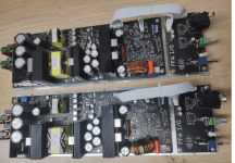
FFA001V3
Output: 2x150W @ 4 / 8ohm
Input: 85--265Vac, constant power SMPS
Size: 90x150mm
Price: $49.9/Unit, w/o shipping (Inc. I/O buffer and mating cables)
FFA001V3-HB
Note: Configured as a high-bass mode. CH1=300W@4OHM and CH2=120W@8OHM, similar to the Pascal U-PRO2
Price: $54.9/Unit, w/o shipping (Inc. I/O buffer and mating cables)
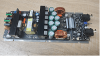
FFA002V2 (1U height)
Output: 2x300W @ 4 / 8ohm
Input: 85--265Vac, constant power SMPS
Size: 95x200mm
Price: $99.9/Unit, w/o shipping (Inc. I/O buffer and mating cables)
FFA003V1
Output: 1x150W @8Ohm / 1x300W @4ohm
Input: 85--265Vac, constant power SMPS, heavy-duty design
Size: 90x245mm
Price: $64.9/Unit (Inc. AL base plate and Volume IO buffer) w/o shipping
PM me if you need more information.
Thanks~
Pics of FFA001V3


Pics of FFA002V2

Pics of FFA003V1

Misc
--- FFA001_V3 spec sheet & Test data;
--- FFA001_V3 & I/O_V1&I/O_V2 dxf file;
--- FFA001_V3 RearPanel_XLR 3D drawings;
--- FFA001_V3 RearPanel_RCA drawing and PDF;
Announce some SMPS+Class D amplifier integrated modules here:
FFA001V3
Output: 2x150W @ 4 / 8ohm
Input: 85--265Vac, constant power SMPS
Size: 90x150mm
Price: $49.9/Unit, w/o shipping (Inc. I/O buffer and mating cables)
FFA001V3-HB
Note: Configured as a high-bass mode. CH1=300W@4OHM and CH2=120W@8OHM, similar to the Pascal U-PRO2
Price: $54.9/Unit, w/o shipping (Inc. I/O buffer and mating cables)
FFA002V2 (1U height)
Output: 2x300W @ 4 / 8ohm
Input: 85--265Vac, constant power SMPS
Size: 95x200mm
Price: $99.9/Unit, w/o shipping (Inc. I/O buffer and mating cables)
FFA003V1
Output: 1x150W @8Ohm / 1x300W @4ohm
Input: 85--265Vac, constant power SMPS, heavy-duty design
Size: 90x245mm
Price: $64.9/Unit (Inc. AL base plate and Volume IO buffer) w/o shipping
PM me if you need more information.
Thanks~
Pics of FFA001V3
Pics of FFA002V2
Pics of FFA003V1
Misc
--- FFA001_V3 spec sheet & Test data;
--- FFA001_V3 & I/O_V1&I/O_V2 dxf file;
--- FFA001_V3 RearPanel_XLR 3D drawings;
--- FFA001_V3 RearPanel_RCA drawing and PDF;
Attachments
-
FFA001_V3_Data_Sheet-20220814.pdf995.4 KB · Views: 533
-
FFA001_V3 Testdata-0802.pdf87 KB · Views: 342
-
FFA001_V3_MechDrawings.rar360.7 KB · Views: 300
-
 FFA003V1.png233.4 KB · Views: 223
 -
 FFA002V2_3.png1.3 MB · Views: 226
 -
FFA001V3_RearPanel_XLR.pdf62.9 KB · Views: 108
-
FFA001V3_RearPanel_XLR.STEP107.4 KB · Views: 76
-
FFA001V3_RearPanle_XLR+IO.STEP7.3 MB · Views: 73
-
FFA001V1_IO_RCA rear BD.pdf13.3 KB · Views: 83
-
FFA001V3_IO_RCA rear BD.zip77.8 KB · Views: 73
Last edited:
Thanks for reaching out, would you mind PM me to leave your mail? I can send you the test data for reference~Technical dat please.
Can it compeed with Hypex modules soundwise?
Appreciate you like it. In fact, it's a very compact design -- we have Main + Aux PSU design for energy saving, we also have the clip limiter circuit integrated and it also has the temperature compressing function on the amplifier sideCertainly is good value!

It can support both the balanced and the unbalanced input.Looks very interesting and carefully designed. Does the module work with unbalanced input?
Thanks,
Eric
What do you mean by high bass mode? Looks to me that Ch 1 will power the woofer and Ch 2 the tweeter/compressiondriver.Hi folks, Thanks for your interest in this module.
Moreover, in addition to stereo, this module can also be configured as a high-bass mode--- CH1=300W@4OHM and CH2=120W@8OHM, similar to the Pascal U-PRO2, and its 26pin input is compatible too.
If so it's an interesting concept.
Kind regards,
Willem.
Hi, WillemWhat do you mean by high bass mode? Looks to me that Ch 1 will power the woofer and Ch 2 the tweeter/compressiondriver.
If so it's an interesting concept.
Kind regards,
Willem.
You're correct. In the high bass mode, CH1 will have more output (300W)to power the woofer, while CH2 will limit its output for the tweeter.
Regarding to this configuration, we need hardware-change the current limit for each output, and this module will be the variant version, which is our original design platform to support our biggest loudspeaker brander.
Thanks
Eric
For a single drive, it's 300W@4ohm at CH1 for high/bass configuration.what is the power output into 4ohms?
For stereo version is 2x 150W @4ohm limited by the output current setting, while 2x150W @8Ohm limited by the output voltage setting.
Thanks,
Erica
Hello friends~
Since many of you are asking about the input buffer board, here, I am making the consistent announcement-- we'll provide the free charge of one set XLR input buffer + the 26pin ribbon cable for each customer.
And, regarding the AL basement, since I just demo to make them together, there is no mounting hole to fix it to your project, I do not think it's useful to you. If you like, I can offer one free sample to the first 10 customers.
Maybe in the future, I'll make the right mount hole for this aluminum plate, then you can put it into your products~~
Thanks,
Erica
Thanks, it's not the chip design, it's the discrete circuit design~Nice design, what chip does it use?
Seems like a nice and interesting design.
I would only really like to see the mosfets on the other side of the board.
Which give much better thermals as well as better system integration.
(easy to mount on a plate for example)
Would it also be possible to show the THD+N charts in the more conventional way, it's rather confusing atm?
I would only really like to see the mosfets on the other side of the board.
Which give much better thermals as well as better system integration.
(easy to mount on a plate for example)
Would it also be possible to show the THD+N charts in the more conventional way, it's rather confusing atm?
Hi, b_forceSeems like a nice and interesting design.
I would only really like to see the mosfets on the other side of the board.
Which give much better thermals as well as better system integration.
(easy to mount on a plate for example)
Would it also be possible to show the THD+N charts in the more conventional way, it's rather confusing atm?
Yes, the output MOSFET + rectifier diode was screwed on the heatsink with the insulated ceramic plate, which was well dissipated by this tooled Heatsink, I'm glad you like it
To explain the THD+N data, I test the 100/1k/6.65K frequency with output power from 0 to rated output @4/8ohm, and each frequency with a different color to be marked in the test data.
Thanks,
Eric
- Home
- Vendor's Bazaar
- 2x150W Amp module for sale