Hi, has anyone tried to build this amp?
Electronics Circuits: Power Amp OCL by 741+2N3055+MJ2955
I bought the printed circuit board and mount it all.
I put in series to power a 100W lamp to limit the current.
But if I keep it on for a few seconds I get out of the smoke from the speaker.
(fortunately cheap speakers for testing)
I can not adjust the bias in the sense that rotating the trimmer in one hand and the other does not change anything.
any ideas?
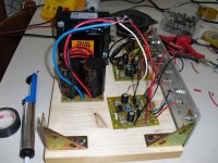
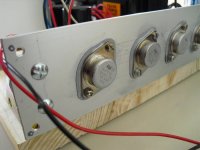
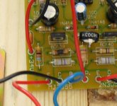
Following are some pictures of my amp under construction / testing
Electronics Circuits: Power Amp OCL by 741+2N3055+MJ2955
I bought the printed circuit board and mount it all.
I put in series to power a 100W lamp to limit the current.
But if I keep it on for a few seconds I get out of the smoke from the speaker.
(fortunately cheap speakers for testing)
I can not adjust the bias in the sense that rotating the trimmer in one hand and the other does not change anything.
any ideas?
Following are some pictures of my amp under construction / testing
Attachments
Last edited:
Hi
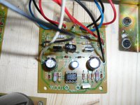
Maybe you have a small mistake somewhere, check the pcb for backward transistor, diode or wrong value, etc.
disconnect the collectors of both TO-3 transistors (the 2 big ones) and measure and record all the DC values. The bias adj should be very minimal in range. BTW, These circuits from that web site are not very good, more like text book experiments.
yes keep the light bulb for safety. no speaker connection until everything checks out.
markup and post schematic with all your measurements.
damn, I just disconnected the two collectors, but with the speaker connected, the result, the lamp is turned on for just a moment and then goes off so it's a good sign, unfortunately I saw a beautiful cloud of white smoke from the transistor BD139
I do not have an electric schematic, the website has the schematic
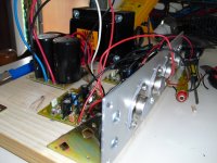
Just looking at your very good images, I can NOT see that you used two (2) insulating nylon shoulder washers for the TO-3 mounting screws. The case (collectors) of both transistors should have very high ohm resistance to the heatsink. BTW your heat sink as shown is probably way too small!
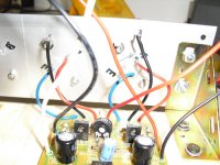
isolations of the two power transistors are ok!
the insulation of the transistors are mounted at the top to the contrary in order to connect the collectors.
if the heatsink is too small at most there would be a substantial heating not you agree?
the insulation of the transistors are mounted at the top to the contrary in order to connect the collectors.
if the heatsink is too small at most there would be a substantial heating not you agree?
Attachments
Last edited:
Because this is a cfp topology (very primitive) and oscilates badly try to use compensation caps (local feedback) betweent the base and collector of the driver transistor bd139 and bd140. Start from 680pf and lower the value to 22 pf. if you succed to stay between to 100pf ~ 33pf you will be OK. Otherwise you will probably have a loss of bandwidth. If it still oscilates with 680pf try also to fit caps between the output transistors between the base and the emitter. Th e same method as the driver. As lower value the better.
Good luck
Ps keep the bias current low and increase gradully
Good luck
Ps keep the bias current low and increase gradully
to be precise, the PCB is slightly different from the drawing, there is no capacitor between pin 1 and 8 of the two transistors 741 I have changed the bd139/140 respectively.
but this should not affect the failure
agreed,
mark any part changes on the schematic along with yer DC values. Im looking mainly for the max and min current flowing thru the driver transistors with both the output collectors floating disconnected.
Because this is a cfp topology (very primitive) and oscilates badly try to use compensation caps (local feedback) betweent the base and collector of the driver transistor bd139 and bd140. Start from 680pf and lower the value to 22 pf. if you succed to stay between to 100pf ~ 33pf you will be OK. Otherwise you will probably have a loss of bandwidth. If it still oscilates with 680pf try also to fit caps between the output transistors between the base and the emitter. Th e same method as the driver. As lower value the better.
Good luck
Ps keep the bias current low and increase gradully
yes this maybe a good idea after 1st checkout.
Because this is a cfp topology (very primitive) and oscilates badly try to use compensation caps (local feedback) betweent the base and collector of the driver transistor bd139 and bd140. Start from 680pf and lower the value to 22 pf. if you succed to stay between to 100pf ~ 33pf you will be OK. Otherwise you will probably have a loss of bandwidth. If it still oscilates with 680pf try also to fit caps between the output transistors between the base and the emitter. Th e same method as the driver. As lower value the better.
Good luck
Ps keep the bias current low and increase gradully
you just turn it starts to make strange sounds and then stop the changes that I've conisigliato I will keep this as soon as I can run the amp
The problem now is that I can not keep the amp turned on for more than a few seconds without burning everything ....
The project is primitive? ok I agree, but let me start with something simple, then I think we should not play badly
do not you agree?
agreed,
mark any part changes on the schematic along with yer DC values. Im looking mainly for the max and min current flowing thru the driver transistors with both the output collectors floating disconnected.
ok ok .... but now I have the problem that if I turn the amp burn the transistor BD139
What do I do?
Change the potentiometer to 5K (1 kOhm seems too low)
If max bias setting is too low(lower than 50 mA), then change the two 15K resistors to 10k
When I ran the circuit in SPICE, using 5K pot
I could adjust from 50mA bias and lower.
disagree
the bias need to lower than 50mA
changing the diodes is good for that
NO, wrong!
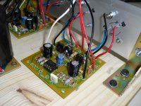
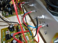
not burn the transistor but the resistance as shown in the picture.
So, what to change the trimmer 5k put two 680pf capacitors or other value between the base and collector of the two driver transistors,
and if I changed the two transisto with:
BD139> BC140 - BD140> BC161?
What do you think?
not burn the transistor but the resistance as shown in the picture.
So, what to change the trimmer 5k put two 680pf capacitors or other value between the base and collector of the two driver transistors,
and if I changed the two transisto with:
BD139> BC140 - BD140> BC161?
What do you think?
Attachments
Last edited:
Design myths.
Generally speaking, there is nothing wrong about cfp ( aka Sziklai topology ).
The wrong design is: cfp output stage with gain.
Read this, "Design to avoid" see figure 15.
Elliott Sound Products - Audio Power Amplifier Design Guidelines.
Generally speaking, there is nothing wrong about cfp ( aka Sziklai topology ).
The wrong design is: cfp output stage with gain.
Read this, "Design to avoid" see figure 15.
Elliott Sound Products - Audio Power Amplifier Design Guidelines.
- Status
- This old topic is closed. If you want to reopen this topic, contact a moderator using the "Report Post" button.
- Home
- Amplifiers
- Solid State
- 2n3055 + mj2955 ampli