ok, something starts to go the right way, I put two resistors of 100 hom (the first ones that have happened to me)
I changed the two diodes 1N4148 to 1N4007 (I had those ...)
I have the positive 18v and negative 32v! possible? of course after the two resistors
up trimmer I have respectively 8 and 9 v
I still have no heat or burn the speaker wires disconnected and unplugged for collectors.
I changed the two diodes 1N4148 to 1N4007 (I had those ...)
I have the positive 18v and negative 32v! possible? of course after the two resistors
up trimmer I have respectively 8 and 9 v
I still have no heat or burn the speaker wires disconnected and unplugged for collectors.
Last edited:
this is the end ....
I removed the two resistors 100 hom
I connected the collectors
and ... the lamp is on, I have noise from speaker
and the bias that is not responding!
I have left to put the two capacitors between B and C of the two transistors ponso pilot but that will solve .....
I finished the ideas .....
I removed the two resistors 100 hom
I connected the collectors
and ... the lamp is on, I have noise from speaker
and the bias that is not responding!
I have left to put the two capacitors between B and C of the two transistors ponso pilot but that will solve .....
I finished the ideas .....
Last edited:
cannot measure yet ? see post#10
ok, tomorrow I will do readings now it's dinner time
thanks again
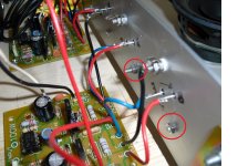
You have put insulators under the output transistors, but it doesnt look like youve put insulators under both fixing screws for these. See pic
Tony
That was my observation as well. see post #7
The circuit is missing a couple resistors. There should be emitter resistors for 3055/2955, 0.2 - 0.5 Ohm. How can you determain how much current is flowing in the outputs without this resistor or an amp-meter in series with the output transistor emitter? Due to the high transconductance of BJTs this resistor is necessary to maintaining a stable bias.
Figure from the datasheet, Hfe for this device is 50 @ 50mA bias, then 1mA of base current is required. The BD139/140 bias is, or must be greater than 1mA so the outputs saturate. A resistor is needed from the base to the rails of the 3055/2955 in order to prevent them from saturation and smoke. Voltage across this resistor will be ~0.7V. Figure the value by whatever current you want to bias in BD139/140 drivers.
There are two types of compensation needed for stable CFP amp with BJTs. Frequency compensation to prevent oscillation instability and thermal compensation to prevent thermal run-away. In the CPF it is the drivers that need to be thermally compensated not the outputs. The BD139/140 should be mounted on a small piece of metal along with the biasing diodes. Due to the proximity of the places on the PCB for these components it should be an easy modification. Adding the missing resistors shouldn't be that hard either. I would not expect spectaular perfomance form such a simplistic design but it should at least work with a few mods.
qualcuno ha provato a costruire questo amplificatore? ho comperato dei circuiti stampati ed ho montato il tutto.
Forse cercavi: come già detto l'isolamento dei due transistor TO3 rispetto alla piastra di alluminio è isolato. ho controllato con il tester
Digita il testo o l'indirizzo di un sito web oppure traduci un documento.
Annulla
Ascolta
Trascrizione fonetica
Traduzione da italiano verso inglese
as already mentioned the isolation of two transisto TO3 compared to aluminum plate is isolated.
I checked with the tester and between EBC and the aluminum plate is isolated.
maybe you can not see well, but I'm sure it's right. in any case, tomorrow I will do the following changes and again the following tests:
1) change the resistance from pin 6 of the 741 goes to the two diodes from 47 to 5 hom hom.
2) change the resistance from 12-15k or 10k
3) I put two condensers 680 pF between B and C of the two driver transistors.
I have already changed in the two diodes 1N4148 and 1N4007 1k trimmer to 4.7 k
I will do readings without connecting collectors with two resistors from 220 to hom 5W + / - supply and without connecting the speaker and see ...
The circuit is missing a couple resistors. There should be emitter resistors for 3055/2955, 0.2 - 0.5 Ohm. How can you determain how much current is flowing in the outputs without this resistor or an amp-meter in series with the output transistor emitter? Due to the high transconductance of BJTs this resistor is necessary to maintaining a stable bias.
Figure from the datasheet, Hfe for this device is 50 @ 50mA bias, then 1mA of base current is required. The BD139/140 bias is, or must be greater than 1mA so the outputs saturate. A resistor is needed from the base to the rails of the 3055/2955 in order to prevent them from saturation and smoke. Voltage across this resistor will be ~0.7V. Figure the value by whatever current you want to bias in BD139/140 drivers.
There are two types of compensation needed for stable CFP amp with BJTs. Frequency compensation to prevent oscillation instability and thermal compensation to prevent thermal run-away. In the CPF it is the drivers that need to be thermally compensated not the outputs. The BD139/140 should be mounted on a small piece of metal along with the biasing diodes. Due to the proximity of the places on the PCB for these components it should be an easy modification. Adding the missing resistors shouldn't be that hard either. I would not expect spectaular perfomance form such a simplistic design but it should at least work with a few mods.
I agree that two resistor are missing, but unfortunately I have not designed this ampli.
for other explanations, I agree that if the polarization of the transistor must be a specific value, and it would be nice to check and verify certain values and currents.
But unfortunately now I'm at a stage when I turn there's something burning ....
Did you read this from the link I gave in post #20
Designs to Avoid There are some designs that should simply be avoided. Two in particular are shown here, but this doesn't mean that there aren't others as well. The two shown below suffer from a number of problems, with the biggest issue being thermal stability. This is by no means all though - the first to avoid is shown in Figure 14, and includes a compound (Sziklai) pair for comparison. As you can see, the "output stage with gain" (output 1) simply breaks the feedback loop within the compound pair and adds resistors. The gain is directly proportional to the resistor divider ratio, so the gain is 3.2 with 220 ohms and 100 ohms as shown. The problem is that this applies to DC as well as AC, so the stage amplifies its own thermal instability. Because of the relatively high output impedance, the actual gain will be less than calculated.
Figure 15 - Output Stage with Gain (Sziklai Pair for Comparison) Why would anyone bother? The stage has the advantage that having gain, so it can be driven directly by an opamp whose output level would normally be too low to be useful. Several amplifiers have been built using this circuit over the years, and all those I have seen have been thermally unstable, and some also have high frequency instability issues. Because the output stage local feedback is reduced by the amount of gain used, distortion is significantly higher than with a conventional compound pair (for example). In the above circuits, the stage with gain has an open loop distortion of 4%, while the compound pair stage has distortion less than 0.1%. This was simulated using an 8 ohm load - in reality, the distortion difference is usually greater than this, with the gain version showing even higher distortion. A vast amount of negative feedback is needed to make the circuit linear enough to be usable. As noted above, output impedance is also much higher than the compound pair.
Designs to Avoid There are some designs that should simply be avoided. Two in particular are shown here, but this doesn't mean that there aren't others as well. The two shown below suffer from a number of problems, with the biggest issue being thermal stability. This is by no means all though - the first to avoid is shown in Figure 14, and includes a compound (Sziklai) pair for comparison. As you can see, the "output stage with gain" (output 1) simply breaks the feedback loop within the compound pair and adds resistors. The gain is directly proportional to the resistor divider ratio, so the gain is 3.2 with 220 ohms and 100 ohms as shown. The problem is that this applies to DC as well as AC, so the stage amplifies its own thermal instability. Because of the relatively high output impedance, the actual gain will be less than calculated.
An externally hosted image should be here but it was not working when we last tested it.
Figure 15 - Output Stage with Gain (Sziklai Pair for Comparison)
Hi
SUrely it depends?? IN the circuit (Fig 15 left) the bias voltage needed by Q2, Q3 will be increased because of the ~400mV needed across R12, R13 to give ~600mV across R6, R7. Therefore, the voltage coefficient in Q1 is going to be about -6.7 mV/C. The voltage across R6, R7 will therefore fall and be approximately the -2 mV/C needed for thermal stability. My conclusion: as long as all transistors Q1-Q5 are on the same heatsink this circuit should be thermally stable.
On the right, surely the resistors R8 and R9 should be in the collectors of the output/emitters of the driver. Then, Q1 should be thermally coupled to Q2, Q3 and do not need to be coupled to Q4, Q5.
John
If you want to drive the driver/outputs directly with an op amp, you need to use the "QSC" topology. Hook up the "good" circut as shown (unity gain). Ground what is normally the output node, and connect the speaker out to the center tap of the power supply, effectively reversing the output phase. Swap everything associated with the feedback connections - connect feedback sense to the "new" speaker out, and switch the roles of the + and - inputs (to re-invert the phase). It's quick, dirty, and it works. Much more stable than the Tiger. And doesn't sound bad if you can keep the Iq relatively constant with temp. You will, however, need separate power supplies for each channel.
This works.
From Opamp Based Power Amp
Figure 1 - Power Amplifier Schematic
From Opamp Based Power Amp
An externally hosted image should be here but it was not working when we last tested it.
Figure 1 - Power Amplifier Schematic
This works.
Yes, limited to about 10 watts. Higher rails give no more output.
If you want to drive the driver/outputs directly with an op amp, you need to use the "QSC" topology. Hook up the "good" circut as shown (unity gain). Ground what is normally the output node, and connect the speaker out to the center tap of the power supply, effectively reversing the output phase. Swap everything associated with the feedback connections - connect feedback sense to the "new" speaker out, and switch the roles of the + and - inputs (to re-invert the phase). It's quick, dirty, and it works. Much more stable than the Tiger. And doesn't sound bad if you can keep the Iq relatively constant with temp. You will, however, need separate power supplies for each channel.
i believe this is what you mean:
An externally hosted image should be here but it was not working when we last tested it.
An externally hosted image should be here but it was not working when we last tested it.

Bingo.i believe this is what you mean:
you are making part value changes that are contrary to one another ie bias.
It can be done with simple rearrangement of the OP's circuit (and dropping a couple resistors, actually). You'd bias it the same way.
Bingo.
It can be done with simple rearrangement of the OP's circuit (and dropping a couple resistors, actually). You'd bias it the same way.
by separate supplies, do you mean separate power transformer windings? i have seen local implementation of this topology and to be honest i politely reject such amps that are sent to my shop for repairs.....
- Status
- This old topic is closed. If you want to reopen this topic, contact a moderator using the "Report Post" button.
- Home
- Amplifiers
- Solid State
- 2n3055 + mj2955 ampli