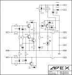
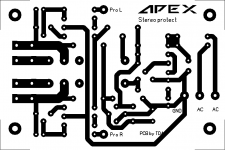
Stereo DC and overload protect
Hi Mile, can you share the pcb?
Hi Mile, can you share the pcb?
It is not my PCB design... use this.
Attachments
Stereo DC and overload protect
What is the max VAC supply voltage?
It is not my PCB design... use this.
A home etching friendly version?
What is the max VAC supply voltage?
2x40vac
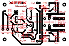
apex stereo protect
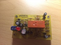
Here's the .lay file for the stereo protect")
This one is adapted to an single 15VAC secondary as an PSU,for higher voltages another relay and it's backing resistor value should be changed
On the sidenote,I built that FH11 in the post above
Here's the .lay file for the stereo protect
This one is adapted to an single 15VAC secondary as an PSU,for higher voltages another relay and it's backing resistor value should be changed
On the sidenote,I built that FH11 in the post above
Attachments
Last edited:
Nice built FH11,
Thanks for the DC protect.
Thanks for the DC protect.
Here's the .lay file for the stereo protect
This one is adapted to an single 15VAC secondary as an PSU,for higher voltages another relay and it's backing resistor value should be changed
On the sidenote,I built that FH11 in the post above
Here's the .lay file for the stereo protect
This one is adapted to an single 15VAC secondary as an PSU,for higher voltages another relay and it's backing resistor value should be changed
On the sidenote,I built that FH11 in the post above
Thanks for sharing...
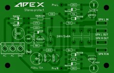
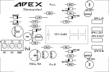
I redrew it also, for anyone that may want it. I included gerber files and pdf's.
Attachments
FH11 in action.
YouTube
What bias current did you adjust the FH11 for?
That is: the current or voltage on R15A.
Apex,
I have simulated the FH11 on LTSpice, trying several bias currents.
That's why I wanted to know the bias you used to get 0.045% THD @ 1KHz, getting 225watts for 8ohm load, and 60v p-p.
For 8ohms it would be impossible to get 225 watts with a +/-60v supply. What I get at 8ohms is 142 watts for 1KHz, and 0.004% THD. That is at pre-clipping levels.
Not superb, compared with a Honeybadger, for instance, but decent.
What I found is that output could be improved if the LTP THD is improved. In most designs I have simulated, the LTP was very good until it went through the VAS.
Which of your LTP inputs has lower THD?
What bias current did you adjust the FH11 for?
That is: the current or voltage on R15A.
It was set at 10mV over the gate resistors
- Home
- Amplifiers
- Solid State
- 100W Ultimate Fidelity Amplifier