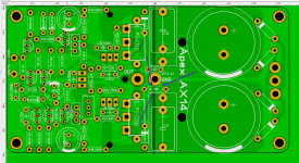
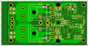
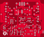
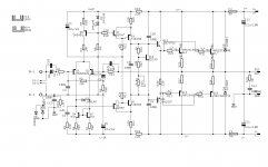
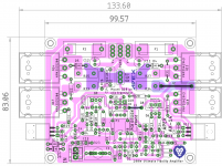
Hi. Мake an amplifier layout, was parallel to the radiator. Please see if everything is correct and important, here is the 10 Ohm resistor. Do I understand correctly that it should be (as well as the capacitor C13) combined signal and power ground?
An externally hosted image should be here but it was not working when we last tested it.
An externally hosted image should be here but it was not working when we last tested it.
Attachments

Last edited:
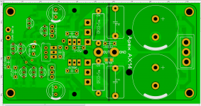
So... 100mm long for China manufacturer -)))
transistors smd... just too lazy -))))
there is only one question left. 10ohm resistor is needed to combine the signal and power ground?
transistors smd... just too lazy -))))
there is only one question left. 10ohm resistor is needed to combine the signal and power ground?
Attachments
Last edited:
So... 100mm long for China manufacturer -)))
transistors smd... just too lazy -))))
there is only one question left. 10ohm resistor is needed to combine the signal and power ground?
Hello Astaro,
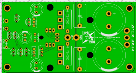
Nice layout. Do consider mechanical mounting convenience of o/p devices.
Also MBRS1100 @ 1amp might be a little weak for this amp. I could be wrong also.
")
regards
Prasi
prasi Thank you for compliment.
just in case will install MBRS2H100T3G. (100V, 2A)
And how about resistor? it is needed?
keep the resistor as an option, if you experience hum issues , you could experiment with OR without resistor (jumper in place of resistor).
regards
Prasi
I believe in the original design, the input ground joined the power ground at the PSU and there was no 10ohm resistor.
It is still the case. This resistor is there for safety reasons; like when people forget to tie the input gnd to the supply ground at first power up (wasn't the original value 10 ohms instead of 100 ohm?)
And yes, I too believe it is the better way to wire power gnd and input ground separate to the power supply gnd.
prasi Thank you for compliment.
just in case will install MBRS2H100T3G. (100V, 2A)
And how about resistor? it is needed?
Even 2A will not cut it. The AX14 amp is rated at:
* 80 watts in 8 ohms: you'll need at least 3,2 A
* 100 watts in 4 ohms: you'll need at least 5 A
Way better to use diodes who have a large safety margin. You could use something like a BYV42.
About the resistor, see my previous post. It is there for safety reasons but since you are including the power supply on the amp pcb you should short the resistor and make sure you have a direct trace from the input ground to your "star ground" on the pcb.
What kind of caps will you be using on the power supply section?
What are the specs of your transformer?
prasi Thank you for compliment.
just in case will install MBRS2H100T3G. (100V, 2A)
And how about resistor? it is needed?
you could consider using PB3508-E3/45 Vishay Semiconductors | Mouser India
its vertical SIP-4 package and takes little space and you could make provision for aluminium bracket as a heatsink. Although, it will be fine w/o bracket for normal home use. Just a suggestion, which you could ignore as well
.If you want smd packages only, consider using bridge formed by using DPAK smd rectifier diodes. https://www.mouser.in/datasheet/2/389/stth806-956966.pdf
regards
Prasi
Last edited:
I have the transformer, it after rectification gives 2 x 30 Volts (160 Watts). It so small voltage to put something instead of the Schottky. And 2 Watt diodes, I think, enough. I will not organize a disco at home-)) may be I 'll find 3 watt diodes Schottky -))) I will think about it. Nowhere to hurry.
I have the transformer, it after rectification gives 2 x 30 Volts (160 Watts). It so small voltage to put something instead of the Schottky. And 2 Watt diodes, I think, enough. I will not organize a disco at home-)) may be I 'll find 3 watt diodes Schottky -))) I will think about it. Nowhere to hurry.
Sure, I would simply advice to select diodes who can handle at the very very very least 4 amps. This way your safe on the power supply side (I guess your transformer is rated around 4 amps). If you want to keep it simple and small then the bridge rectifier Prasi mentioned is a good alternative.
Even if you think you will not turn up the volume too much, you never know how many amps your amp is drawing at a given time. It would be a shame to blow up the power supply by accident. There are other issues to consider: if you don't have a speaker protection you could easily blow up your speakers in the process. The AX14 amp deserves a good power supply.
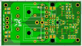
I have it shared here. You may download gerbers.
W61084ASN13_apex ax14_total new_2pairs_rev1- Share Project - PCBWay
let me know if its not convenient, I can post here as well.
regards
Prasi
Dear Prasi,
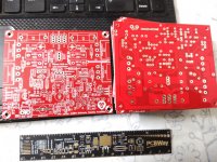
Thank for the Gerber files. I am interested in this one. Has it been built yet? The PCB works OK?
I'm also looking for the schematic for this one, I think this one contains more parts than the original APEX AX14 schematic. I have seen it on the link above but the schematic on that link is not readable and it's not in the downloaded zip files.
Could you please post in the forum or direct me to where it has been posted?
Thank!
Regards,
Chatchai
Hello Chatchai,Dear Prasi,
Thank for the Gerber files. I am interested in this one. Has it been built yet? The PCB works OK?
I'm also looking for the schematic for this one, I think this one contains more parts than the original APEX AX14 schematic. I have seen it on the link above but the schematic on that link is not readable and it's not in the downloaded zip files.
Could you please post in the forum or direct me to where it has been posted?
Thank!
Regards,
Chatchai
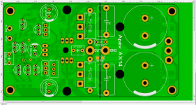
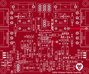
Please find attached herewith the stuffing guide and sch. It only contains ground lift components (10R+ anti parallel diodes as an option) as additional. These can be also left out and i/p ground can be connected to PSU ground as per original APEX advice.
Also it is with 2 pairs of o/p devices.
Otherwise the schematic follows the original AX-14. I am collecting the parts to build it.
regards
Prasi
Attachments
Last edited:
- Home
- Amplifiers
- Solid State
- 100W Ultimate Fidelity Amplifier