Is this circuit (on post 1) adaptable to be powered by -85V, 0V, +85V power supply? I think, I should be able to replace its input stage with a Complementary Feedback Pair and replace some transistors with others that are rated for higher voltages.
Why are there TWO grounds one for signal and one for power? Are these electrically isolated?
Why are there TWO grounds one for signal and one for power? Are these electrically isolated?
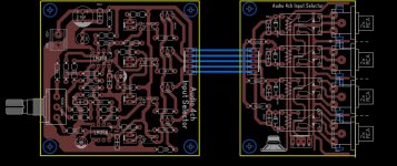
I im searching for this pcb in this thread and could not find post who made this nice pcb of input selector...could someone find what post is this so that i can contact author for gerbers or lay6 file.
View attachment APEX Audio input Selector.zip
I im searching for this pcb in this thread and could not find post who made this nice pcb of input selector...could someone find what post is this so that i can contact author for gerbers or lay6 file.
Attachments
My A9 singing
Hi to All
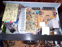
Finally my A9 working.
I used my old Sony TA-F261RI and I replaced PSU, protector and STK 4182 with two A9.
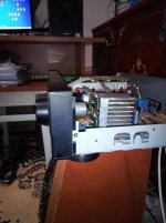
It remains to build the fan controller, at the low volume of the amplifier, the fan is noisy.
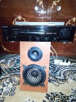
I usually use the Sony TA-FE330 and compared to A9, the sound of A9 is better. For almost the same sound, Sony use bass and treble to maximum, to A9 is not needed. Sony has a flat sound compared to A9 in all frequencies: low, medium and high. A9 also has a better voice stamp and stereo effects have higher amplitude. The comparison is made with the same speakers and signal source.
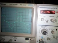
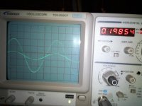
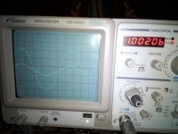
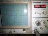
Rail is +/- 35.6 V dc stabilized, offset 1.3 mV, 48 mA bias. I'm attaching a couple of photos during the tests. On the oscilloscope the signal source is directly connected to the A9 input. For input I have 0.5 V pp (0.5 V / division) and output about 50 V pp (10 V / division) and perfect sinus forms at 1 kHz, 20 Hz and 21 kHz.
Thanks to Mr. Miles for this great amplifier. Now I'm listening to my favorite music on the Sony A9") which offers a higher quality audition than the other Sony. The sound space and the stereo effects are excellent.
which offers a higher quality audition than the other Sony. The sound space and the stereo effects are excellent.
Regards
Cornel
Hi to All
Finally my A9 working.
I used my old Sony TA-F261RI and I replaced PSU, protector and STK 4182 with two A9.
It remains to build the fan controller, at the low volume of the amplifier, the fan is noisy.
I usually use the Sony TA-FE330 and compared to A9, the sound of A9 is better. For almost the same sound, Sony use bass and treble to maximum, to A9 is not needed. Sony has a flat sound compared to A9 in all frequencies: low, medium and high. A9 also has a better voice stamp and stereo effects have higher amplitude. The comparison is made with the same speakers and signal source.
Rail is +/- 35.6 V dc stabilized, offset 1.3 mV, 48 mA bias. I'm attaching a couple of photos during the tests. On the oscilloscope the signal source is directly connected to the A9 input. For input I have 0.5 V pp (0.5 V / division) and output about 50 V pp (10 V / division) and perfect sinus forms at 1 kHz, 20 Hz and 21 kHz.
Thanks to Mr. Miles for this great amplifier. Now I'm listening to my favorite music on the Sony A9
which offers a higher quality audition than the other Sony. The sound space and the stereo effects are excellent.Regards
Cornel
Attachments
-
 pf_1530806856.jpg120.8 KB · Views: 457
 -
 pf_1530806643.jpg50.6 KB · Views: 332
 -
 pf_1530806530.jpg89.3 KB · Views: 314
 -
 pf_1530806153.jpg88.7 KB · Views: 210
 -
 pf_1530806064.jpg71.2 KB · Views: 221
 -
 pf_1530805916.jpg72 KB · Views: 226
 -
 pf_1530805785.jpg81.3 KB · Views: 1,074
 -
 APEX Stereo DC and OL protect.JPG244 KB · Views: 1,140
 -
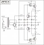 APEX Regulated PSU.jpg239.4 KB · Views: 1,209
 -
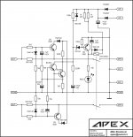
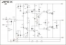 APEX AA9sch.JPG396.8 KB · Views: 1,262
Hello Cornel,
Congratulations on the success and that you were able to solve the problem and enjoying the sound.
So which one you used finally irf540 or irfp240?
For the fan noise, you could use an appropriate value power resistor to slow it down to the desired level so that there is enough cooling at the same time lower noise.
regards
Prasi
Last edited:
Hello Cornel,
Congratulations on the success and that you were able to solve the problem and enjoying the sound.
So which one you used finally irf540 or irfp240?
For the fan noise, you could use an appropriate value power resistor to slow it down to the desired level so that there is enough cooling at the same time lower noise.
regards
Prasi
Hi Prasi,
I used irf 540/9540. For fan control I will use Mr. Mile's schematic. The fan start up to 50 degrees and to this temperature the power of amp will be large enough to cover the fan noise.
The second time I replaced the IRF's, I built the regulated PSU because I thought I had too much rail, I set biass close to 50 mA, and I connected the signal source because I was very curious to listen to the stereo sound.
After one minute IRF's burned. Even now I do not know what the problem was.
I found that the resistance of 10 R on positive rail and 4r7 in Zobbel was brown. I think I had the sea oscillations at the exit, but I did not have time to test with the oscilloscope.
For the third time I replaced all the transistors, I checked the other components and the spaces between the PCB routes and the success ..... I lost two battles but I won the war
I am thinking of building A9 with two pairs of IRFs
Regard
Cornel
Attachments
Hello Cornel,
Congratulations on the success and that you were able to solve the problem and enjoying the sound.
So which one you used finally irf540 or irfp240?
For the fan noise, you could use an appropriate value power resistor to slow it down to the desired level so that there is enough cooling at the same time lower noise.
regards
Prasi
Hi Prasi,
Thanks for your appreciation, suggestions and help,
Regards
Cornel
Hi to All
Finally my A9 working.
I used my old Sony TA-F261RI and I replaced PSU, protector and STK 4182 with two A9.
It remains to build the fan controller, at the low volume of the amplifier, the fan is noisy.
I usually use the Sony TA-FE330 and compared to A9, the sound of A9 is better. For almost the same sound, Sony use bass and treble to maximum, to A9 is not needed. Sony has a flat sound compared to A9 in all frequencies: low, medium and high. A9 also has a better voice stamp and stereo effects have higher amplitude. The comparison is made with the same speakers and signal source.
Rail is +/- 35.6 V dc stabilized, offset 1.3 mV, 48 mA bias. I'm attaching a couple of photos during the tests. On the oscilloscope the signal source is directly connected to the A9 input. For input I have 0.5 V pp (0.5 V / division) and output about 50 V pp (10 V / division) and perfect sinus forms at 1 kHz, 20 Hz and 21 kHz.
Thanks to Mr. Miles for this great amplifier. Now I'm listening to my favorite music on the Sony A9
Regards
Cornel
Nice work,
Regards
Nice work,
Regards
Thanks Mr. Mile.
The bass of A9 is special. Please post a schema for a 2.1 system. Sure it will be an excellent system. Thank you again.
Regard
Cornel
I would suggest to use a thermistor or a diode to detect temperature. Then use that signal to control the motor's speed.
Hi edbarx
Thanks for your suggestions and help.
I have schematic for fan control (see post 10449). I have some audio experience but I do not know how to design scematics like Mr. Mile. For speed control I do not have a schematic.
Regards
Cornel
What you really need is patience. Connect a small power transistor in common emitter configuration, that is, with the emitter connected to ground. Connect the fan motor to its collector with the other terminal connected to the appropriate supply terminal. As a control sensor use a thermistor with a negative coefficient. Use another fixed resistor in series with the thermistor. The thermistor-resistor chain should be connected between base and power supply terminal. Experiment with some resistor values so that the fan runs slowly when the temperature is low and increases speed as temperature rises. (Place a reverse biased diode across the transistor to prevent back emfs from the motor from destroying it.)Hi edbarx
Thanks for your suggestions and help.
I have schematic for fan control (see post 10449). I have some audio experience but I do not know how to design scematics like Mr. Mile. For speed control I do not have a schematic.
Regards
Cornel
Alternatively, you can use a diode as a sensor for temperature. At constant current the voltage across a diode drops by about 2mV/K (K = Kelvin or Celcius). If you use a diode as a sensor you need a different circuit.
What you really need is patience. Connect a small power transistor in common emitter configuration, that is, with the emitter connected to ground. Connect the fan motor to its collector with the other terminal connected to the appropriate supply terminal. As a control sensor use a thermistor with a negative coefficient. Use another fixed resistor in series with the thermistor. The thermistor-resistor chain should be connected between base and power supply terminal. Experiment with some resistor values so that the fan runs slowly when the temperature is low and increases speed as temperature rises. (Place a reverse biased diode across the transistor to prevent back emfs from the motor from destroying it.)
Alternatively, you can use a diode as a sensor for temperature. At constant current the voltage across a diode drops by about 2mV/K (K = Kelvin or Celcius). If you use a diode as a sensor you need a different circuit.
Hi edbarx
The ingenious solution for speed control and is not complicated. I'll test it on a test board and add it to the fan. Thank you again.
Regards
Cornel
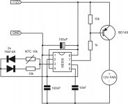
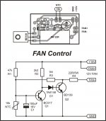
Use this PWM fan speed control
Hi Mr. Mile
Nice schematic as usual. Variable pulses at output 555 dependent on NTC resistance and variable fan speed. Elegant solution. Thanks!
Regards
Cornel
Use this PWM fan speed control
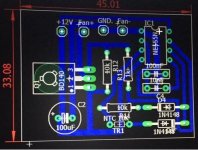
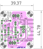
Another option for fan control. Could be useful for my AX-14 2 pair.
Attachments

- Home
- Amplifiers
- Solid State
- 100W Ultimate Fidelity Amplifier