AX11TEF work without Vbe multiplier only 2SC5200 and 2SA1943 must be on heatsink.
You can use MJE340/350 instead MPSA42/92 and 2SC4793/2SA1837 instead MJE340/350, I suggest to add 3 more pairs of outputs and replace BC546 with 2N5551 to get 500W amp.
ApexAudio:
This looks interesting as I am looking for an amp for my bass horn and need the big watts. Can you please post a schematic showin this variation for 500w? What kind of transformer rating in VA and secondary voltage is needed?
Can someone point me to where the latest (confirmed) PCB or sprint file design for the AX11TEF is? This looks interesting - what does having 3 output stage devices do for the maximum power?
I am not aware of AX11 TEF layout (didnt find it), but someone mentioned that bimo's mod AX11 is nice .
reg
prasi
Ben,
Thanks - if you have a catalog of the amps and locations in thread like an index that would be helpful if you can post the index and we can ask ApexAudio to either add it to his post 1 as an index or link to it from post 1.
Hi Ben and XRK,
That would be really nice. Mr. Mile can review it regarding which is the best variant and design. this is what this thread needs, a nice "Table of Contents" sort of.
excellent!
Reg
Prasi
ApexAudio:
This looks interesting as I am looking for an amp for my bass horn and need the big watts. Can you please post a schematic showin this variation for 500w? What kind of transformer rating in VA and secondary voltage is needed?
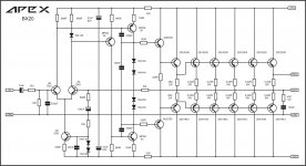
Apex AX11 TEF 5pair = Apex BX20.
I do have AX15TEF 3pair and 4 pair version on sprint, it can be modified to AX11TEF 3 pair and 4 pair version.
Regards
Sonal Kunal
Attachments
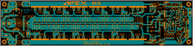
Apex AX11 TEF 5pair = Apex BX20.
I do have AX15TEF 3pair and 4 pair version on sprint, it can be modified to AX11TEF 3 pair and 4 pair version.
Regards
Sonal Kunal
Sonal Kunal,
That's a beautiful layout! Can you please post Gerber files for BX20?
Thanks.
Regards,
X
In Memory of Prince, Be Sociable, Share Sprint files!
In memory of Prince?? I'd rather forget about him ASAP!
FX8 with hexFET mod works
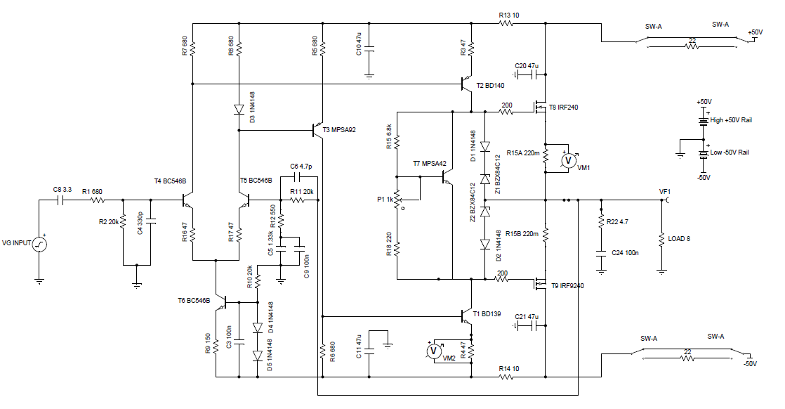
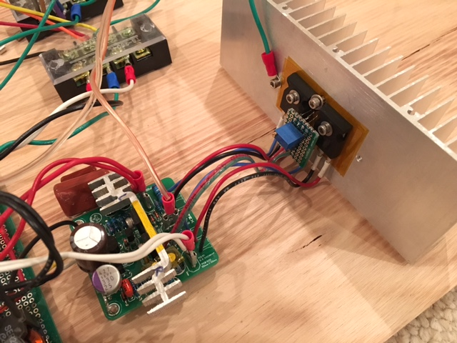
I implemented the above circuit using a small daughter board for the Vbe multiplier with the MPSA42 bolted in between the two output hexFETs. The output devices had to be connected with flying leads as the pinouts are different (S & D swapped on the IRFP240/9240 vs the Hitachi 2SJ/SK's). I used a pair of 10ohm safety resistors in series with the power supply on startup. I adjusted the quiescent bias to 350mA - it likes to run warm. Will have to play with it but so far sound is very good - very powerful sounding and knowing it can take 50v rails is pretty cool.
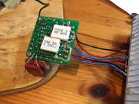
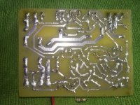
Here is a closeup of the Vbe multiplier daughter board - the flying leads go to the top and bottom of the bias pot location on the board (removed). The bias current is very stable with this Vbe multiplier acting as a thermal compensator:
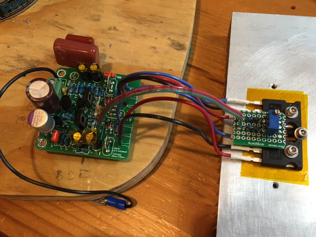
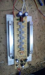
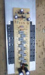
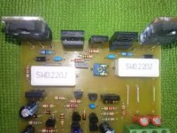
Here are the 0.22ohm source/drain resistors:

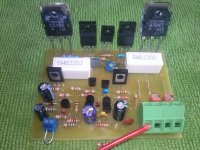
Here is the amp playing music. It's nice when things work like predicted by a sim (nothing blew up and nothing melted). I like it when there is no magic smoke released on first startup :
:
Here are some soundclips of this amp played on a GRS Research XL-S speaker as recorded with a Zoom H4.
Change the .asc extension to .mp3 to listen.
I implemented the above circuit using a small daughter board for the Vbe multiplier with the MPSA42 bolted in between the two output hexFETs. The output devices had to be connected with flying leads as the pinouts are different (S & D swapped on the IRFP240/9240 vs the Hitachi 2SJ/SK's). I used a pair of 10ohm safety resistors in series with the power supply on startup. I adjusted the quiescent bias to 350mA - it likes to run warm. Will have to play with it but so far sound is very good - very powerful sounding and knowing it can take 50v rails is pretty cool.
Here is a closeup of the Vbe multiplier daughter board - the flying leads go to the top and bottom of the bias pot location on the board (removed). The bias current is very stable with this Vbe multiplier acting as a thermal compensator:
Here are the 0.22ohm source/drain resistors:
Here is the amp playing music. It's nice when things work like predicted by a sim (nothing blew up and nothing melted). I like it when there is no magic smoke released on first startup
:
Here are some soundclips of this amp played on a GRS Research XL-S speaker as recorded with a Zoom H4.
Change the .asc extension to .mp3 to listen.
Attachments


Last edited:
I would like to suggest a few changes............
Omit C6 initially and test what it does after first build.
Replace C9 with a pair of inverse parallel 1n4148
Replace D4+D5 with a red LED to indicate ON. Select R9 to suit.
For C8=3u3F, then C5>175uF
Maximum reliable power is approximately: Sum of all output transistors Pmax @ 25°C divided by 4
i.e. one pair of irf240/9240 gives ~ 150*2 / 4 = 75W per channel.
Choose you supply rail voltage (and mains transformer) to roughly equate to that maximum power.
Last edited:
Hello, please help by amplifier AX-14. There is a constant voltage output. I changed transistors, diodes D4 D5 desoldering, I checked all the ingredients, I do not know what to think already. Help.
Attachments
Sonal Kunal,
That's a beautiful layout! Can you please post Gerber files for BX20?
Thanks.
Regards,
X
Gerber files for BX-20. It would be better if pcb is made with 70 Micron or higher copper board.
In Memory of Prince, Be Sociable, Share Sprint files!
BX20 sprint file is posted on#6761.
Attachments
I would like to suggest a few changes.
Omit C6 initially and test what it does after first build.
Replace C9 with a pair of inverse parallel 1n4148
Replace D4+D5 with a red LED to indicate ON. Select R9 to suit.
For C8=3u3F, then C5>175uF
Maximum reliable power is approximately: Sum of all output transistors Pmax @ 25°C divided by 4
i.e. one pair of irf240/9240 gives ~ 150*2 / 4 = 75W per channel.
Choose you supply rail voltage (and mains transformer) to roughly equate to that maximum power.
Hi AndrewT,
I forgot to mention I already omitted C6. C5 is currently 1000uF+330uF OSCON. The LED at D4 and D5 is most welcome as it needs a light to show when on. When you say inverse parallel 4148 do you mean the two 4148's are parallel to each other and then put in place of C9? Is factor of 4 on transistors for factor of safety? If I have forced air cooling of heatsink is that ok to run more power?
Thanks for the feedback and advice!
Last edited:
Gerber files for BX-20. It would be better if pcb is made with 70 Micron or higher copper board.
BX20 sprint file is posted on#6761.
Thank you Sonal Kunal for the Gerbers!

It's not a Factor of Safety................ Is factor of 4 on transistors for factor of safety? If I have forced air cooling of heatsink is that ok to run more power?
Thanks for the feedback and advice!
Both R.Cordell and I came up with a recommendation for output device capability compared to maximum reliable output power that turned out to be quite similar.
Look up his interview series of Threads.
For normal reactive speakers while the heatsink is pretty warm the maximum power that can be reliably obtained is roughly ¼sumPmax.
If you know that you will never run reactive loads and know that your devices never get any warmer than just warm, then you can get more power and get it reliably. Maybe twice as much.
But you have to decide what that amplifier can be used with and at what temperatures.
It's not a Factor of Safety.
Both R.Cordell and I came up with a recommendation for output device capability compared to maximum reliable output power that turned out to be quite similar.
Look up his interview series of Threads.
For normal reactive speakers while the heatsink is pretty warm the maximum power that can be reliably obtained is roughly ¼sumPmax.
If you know that you will never run reactive loads and know that your devices never get any warmer than just warm, then you can get more power and get it reliably. Maybe twice as much.
But you have to decide what that amplifier can be used with and at what temperatures.
Ok, got it. Thanks for the explanation - I will read up on the Cordell stuff.
In the meantime - more listening so far has established that this mod sounds better than the standard FX8 even though vertical MOSFETs are used. The heat output at 350mA is not terrible and current heatsink can handle it passively without a fan. The sound is very powerful and yet clear. I believe distortion is actually less audibly. I need to build a distortion measurement rig for funny loads. So far Inam very happy with it and will proceed to modify the other channel for a stereo pair.
Greetings mr.prasi already i built in apex bx20. Power full sound and i used in pa purpuse it great amp my rail is 65v dc .
Nice build - which PCB design did you go with or is this your own? I am thinking of making this one next.
Hello, please help by amplifier AX-14. There is a constant voltage output. I changed transistors, diodes D4 D5 desoldering, I checked all the ingredients, I do not know what to think already. Help.
You must connect input ground with power ground !
- Home
- Amplifiers
- Solid State
- 100W Ultimate Fidelity Amplifier