If I simply install hexFETs as shown in circuit - would it work per the simulation but with potential for thermal runaway if Vbe multiplier is not used? If I keep current below the 10amps (or whatever spec is) would t be ok?
HexFETs are on order.
It won't work without proper VBE multiplier. Your HEXFETS will self destruct.
If you want a simple amplifier with HEXFETS, you should try Apex A9 amplifier - it consists of just 9 active devices and an opamp.
Here is the reference schematic on which my build is based and also sonal's layout. you could mark up your changes in paint.
reg
prasi
Prasi,
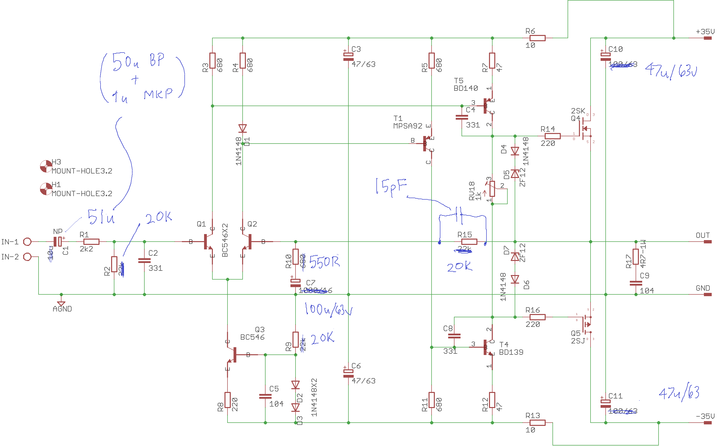
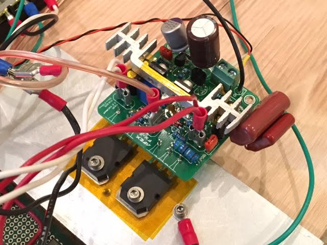
Here is my circuit as built. Thanks for providing the drawing.
X
Attachments
Somethig like this. Not tested, not simulated.
Ok, I simulated this Vbe multiplier circuit and it seems to be ok still. I think HD components went up a bit but still -55dB down at full power.
Here is circuit simulated in TINA (I set the resistor split at Vbe a little differennt, and pot wiper is set at 80%).

I think this might be implemented with flying leads on Vbe multiplier clamped onto the output FET.
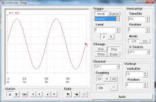
Here is predicted 10kHz sine wave:

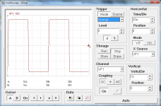
Here is predicted 10kHz square wave:

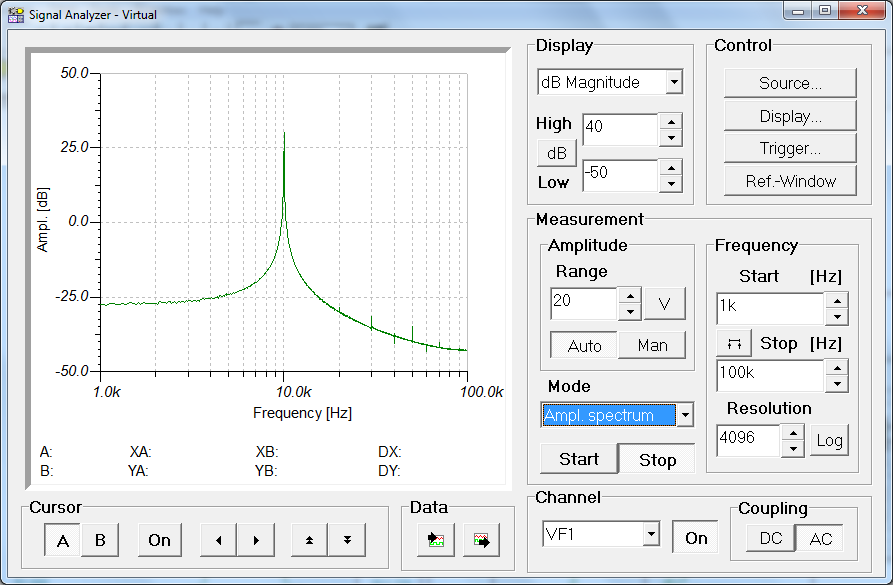
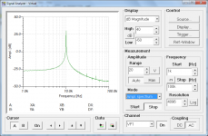
Here is predicted spectrum:
Attachments
I don't know how.Sorry, I am new at this. Would you mind marking up my schematic?
Thanks.
I work with paper and pencil mostly.
ONLY Lateral mosFETs work without a temperature compensator for the output bias current/voltage.If I simply install hexFETs as shown in circuit - would it work per the simulation but with potential for thermal runaway if Vbe multiplier is not used? If I keep current below the 10amps (or whatever spec is) would t be ok?
HexFETs are on order.
BJTs and Vertical mosFETs need a tempco to reduce the tendency for the output bias to wander, sometimes catastrophically.
C1 is far too big.Prasi,
Here is my circuit as built. Thanks for providing the drawing.
X
Use it to set your low frequency band limit.
Typically somewhere between 1Hz and 20Hz.
For the 20k+2k2 your 5u1F gives an LF F-3dB = 0.14Hz
4u7F or 3u3F in MKT, or MKP, would do far better in controlling what audio signal gets through to be processed.
C7 is too small.
It should not have any significant DC voltage across it, nor should it have any significant AC voltage across it.
make C7>= C1*(R1+R2)*sqrt(2)/R10
If you make C1=4u7F, then C7>= 268uF, use 270uF, or 330uF, or 470uF, or even go back to the 1000uF originally shown.
And you image dimensions @ 2,850px × 1,774px are far too big.
Last edited:
Image was just whatever Prasi happened to post - I should have rescaled.
I use a program like "paint" to markup and save image. Then upload to diya server.
size is only 80kB or so
 .
.ONLY Lateral mosFETs work without a temperature compensator for the output bias current/voltage.
BJTs and Vertical mosFETs need a tempco to reduce the tendency for the output bias to wander, sometimes catastrophically.
Is the temperature compensation via T7(IRF540) shown above as suggested by Egra good? Is the idea to use a transistor with a similar temperature coefficient as the Vbe multiplier controlling the bias to servo the bias based on temperature? I guess I don't quite see how an increase in temperature on T7 causes the bias to change in a negative direction? Unless basically the Vbe multiplier in this case causes the voltages between the two driver stages to be lowered (because voltage between them is lowered by virtue of the variable "diode drop" across T7)?
irf540 is not good.
A small transistor that can respond to temperature changes very quickly is required.
That collosal FET will be very slow, if it can ever get near the output FET junction temperature (Tj), but it won't, ever.
I use a To92 next to the output devices, or a sot23 glued to the output's Collector/Drain right next to the plastic package.
irf540 is not good.
A small transistor that can respond to temperature changes very quickly is required.
That collosal FET will be very slow, if it can ever get near the output FET junction temperature (Tj), but it won't, ever.
I use a To92 next to the output devices, or a sot23 glued to the output's Collector/Drain right next to the plastic package.
Can I use a BD139 bolted to the lateral FET? Or should it be the BD140?
the medium power To126 is only a little bit smaller than the To220 FET. It will still be slow.
This all started with D.Self fixing a medium power transistor to the metal case of a To3 output device. He claimed this was the best available way to transfer the Tj to the monitoring sensor.
Many have now taken that advice and started bolting the medium power device to the top of a plastic package output. That is a very different Thermal condition.
Small fast reacting sensors attached INSIDE the power device will always be quicker than any plastic mounted arrangement.
ONsemi and Sanken make some of these internal sensor type output devices. But few use them, so few that ONsemi have stopped making many of their variations on this theme.
Last edited:
So you suggest a TO92 directly attached to the output transistor. Many amps seem to have a TO126 attached to the heatsink in between the two output transistors - seems to work well enough? How fast does it need to respond? I thought the thermal runaway is a circa 0.5 second time response type of condition - i.e., slow feedback is OK? Are you talking about trying to get the thermal mass and resistance low enough for a circa 50msec response to save a thermal runaway?
Just came accross this thread.
Looking to build an amp and this thread seems very popular.
Without reading 720 pages of info, is there a post with shows the different amplifier model so i can choose? Is there a recommended model?
Any info that would be great!
The amp du jour is the FX8 (a MOSFET output stage amp) and the mods to it. It is very simple to build (as are most of Apex Audio's amps in this thread) and the sound is competitive with some of the best out there. Search the thread for the FX8 and you will see several variants. Look for tested builds and get the PCB and schematic. I have not read the whole thread either - but from what I gather, any of the designs submitted by Apex Audio here will please the ear.
From the designer himself, here is his list of favorites, which the FX8 is the best "simple" amp and the A40 is the best "complex" amp. If you want to stick with conventional BJT output stages, the AX11 looks very nice.
http://www.diyaudio.com/forums/soli...imate-fidelity-amplifier-667.html#post4650931
I believe that sot23 glued to the Collector/Drain leadout is the closest to an internal sensor that you can get. If I am right, then this is the only fast monitoring available if you can't get the ONsemt NJLsSo you suggest a TO92 directly attached to the output transistor. Many amps seem to have a TO126 attached to the heatsink in between the two output transistors - seems to work well enough? How fast does it need to respond? I thought the thermal runaway is a circa 0.5 second time response type of condition - i.e., slow feedback is OK? Are you talking about trying to get the thermal mass and resistance low enough for a circa 50msec response to save a thermal runaway?
But that sot23 glued on solution is small and delicate and quite fiddly and will not suit everyone.
Then the Leach diodes drilled into the heatsink probably comes next and you can copy that by drilling a To92 into the heatsink right next to an output device.
Any others are too far away, or have too much thermal resistance in the route from Tj to sensor. Added thermal resistance will add to the delay.
The TO-126 will still do the job of reducing the chance of thermal run-away. It is just slower to react.
I always wondered why they didn't design the Thermal-trak devices with the diode leads in between the three normal leads rather than grouping them on one end. Had they done that they could have been inserted in the same spot as a normal three pin by just trimming the diode legs and running wires. Maybe they would have been more popular.
I always wondered why they didn't design the Thermal-trak devices with the diode leads in between the three normal leads rather than grouping them on one end. Had they done that they could have been inserted in the same spot as a normal three pin by just trimming the diode legs and running wires. Maybe they would have been more popular.
C1 is far too big.
Use it to set your low frequency band limit.
Typically somewhere between 1Hz and 20Hz.
For the 20k+2k2 your 5u1F gives an LF F-3dB = 0.14Hz
4u7F or 3u3F in MKT, or MKP, would do far better in controlling what audio signal gets through to be processed.
C7 is too small.
It should not have any significant DC voltage across it, nor should it have any significant AC voltage across it.
make C7>= C1*(R1+R2)*sqrt(2)/R10
If you make C1=4u7F, then C7>= 268uF, use 270uF, or 330uF, or 470uF, or even go back to the 1000uF originally shown.
And you image dimensions @ 2,850px × 1,774px are far too big.
Ok, I made the input cap a 3.3uF+1.0uF=4.3uF MKT, C1 is now 1000uF/25v + 330uF/25v OSCON. I added a heatsink for the BD139/140's.
Listening to it now as I run sims of a modded hexFET FX8 with an MPSA42 (TO92) as the Vbe multiplier temp compensation. Sounds pretty good so far but need more time with more tracks.
Attachments

Latest FX8 hexFET sim
This latest design seems to work ok but is not ideal. I am using an MPSA42 as the Vbe multiplier temperature compensation. To get low HD though, it needs to pretty much run in hot 'class A' mode with 2.9amps (yikes!) flowing through the hexFETS as measured across the 0.22R collector resistor.
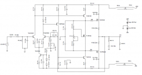
Schematic:
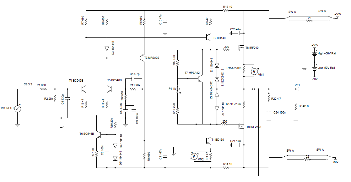
The sims show that it is capable of driving 100w into 8ohms though. The plots below are for a 65w into 8ohms setting except square wave which is 100w.
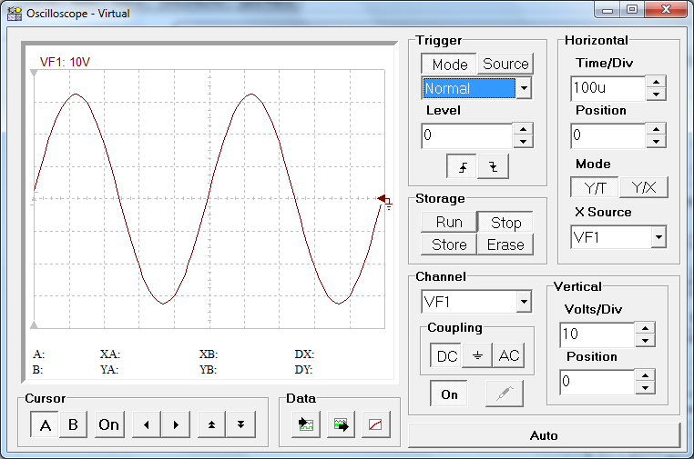
Sine wave at 2kHz:
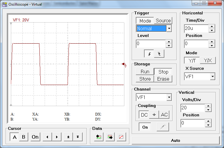
Square wave at 10kHz (100w I think):
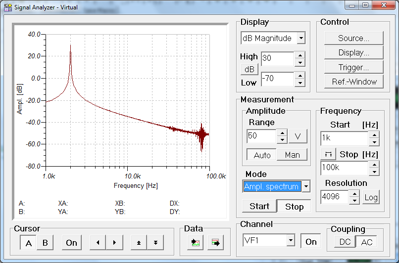
Spectrum Analyzer for 2kHz at 65w:
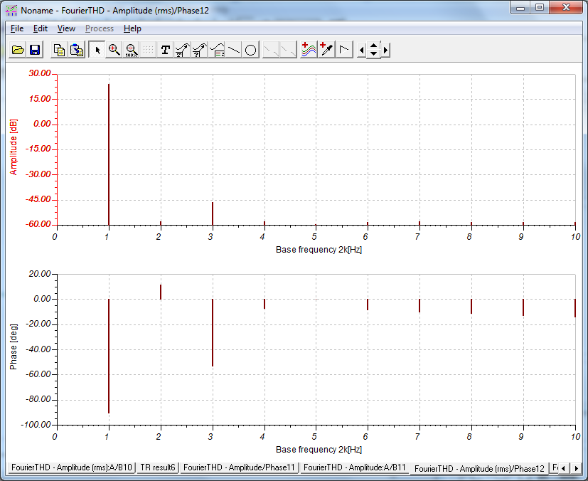
FFT analysis for 2kHz at 65w:
This latest design seems to work ok but is not ideal. I am using an MPSA42 as the Vbe multiplier temperature compensation. To get low HD though, it needs to pretty much run in hot 'class A' mode with 2.9amps (yikes!) flowing through the hexFETS as measured across the 0.22R collector resistor.
Schematic:
The sims show that it is capable of driving 100w into 8ohms though. The plots below are for a 65w into 8ohms setting except square wave which is 100w.
Sine wave at 2kHz:
Square wave at 10kHz (100w I think):
Spectrum Analyzer for 2kHz at 65w:
FFT analysis for 2kHz at 65w:
Attachments
-
 FX8-xrk971-hexFET-Vbe-schematic-v2.png66.1 KB · Views: 6,552
 -
 FX8-xrk971-hexFET-Vbe-Scope-2khz-65w.png51.4 KB · Views: 1,242
 -
 FX8-xrk971-hexFET-Vbe-Scope-square-10khz.png47.6 KB · Views: 1,962
 -
 FX8-xrk971-hexFET-Vbe-Spectrum-Analyzer-2khz-65w.png66 KB · Views: 1,229
 -
 FX8-xrk971-hexFET-Vbe-FFT.png64.8 KB · Views: 1,964
Ok, I made the input cap a 3.3uF+1.0uF=4.3uF MKT, C1 is now 1000uF/25v + 330uF/25v OSCON. I added a heatsink for the BD139/140's.
Listening to it now as I run sims of a modded hexFET FX8 with an MPSA42 (TO92) as the Vbe multiplier temp compensation. Sounds pretty good so far but need more time with more tracks.
i/p cap should be of high quality. Are you sure those are of high quality? there is a wima 4.7u thats generally used in slewmaster builds. you may try that or like I said Nichicon muse BP.
reg
Prasi
Last edited:
- Home
- Amplifiers
- Solid State
- 100W Ultimate Fidelity Amplifier