Add a resistor in parallel to each C, 100uF/63V to power ground.So that's all there is to it? A couple of BC639/40's a 1k resistors?
This sets the multiplier voltage reference (on the transistor base) to a fixed proportion of the input voltage.
Try from 10k giving Vref = 91% of Vin, to 47k giving Vref=98% of Vin.
Last edited:
Best to put a clean PSU in front of the whole amp and keep the FX8 simple. Otherwise just build a different amp. If you add a CM to the circuit it is no longer an FX8
This is most reasonable mod, everything else will harm the amp and its sound.
Hi Gaborbela,
Look at the project 15 (Capacitance Multiplier Supply) from Rod Elliot's pages : it explains very well the capacitance multiplier and even offer a PCb for sale ...
Best regards
rephil
Thanks
I know what is capacitance multiplier, I used it from Elliot website for some of my Class A amplifier like Hiraga monster and Class A.
But there I used it with the whole amp as PS. Here we use a regular PS and that is for the IPS if I am right.
Can these be used at some other amps where usually they use a diode and resistor..
This is most reasonable mod, everything else will harm the amp and its sound.
I disagree. The amp sounds beautiful with just a good clean PSU in front of it. Have you built and tested it to confirm your statement?
It's a pity that prasi's gerber files have one dimension just a little over 100 mm. Some factories offer very good rates for the boards up to 100 mm.
Hi ivanlukic,
Oh! I see. I hadnt given much thought to that aspect. I will change it to 100 by moving things around. Here in india quotes are based on square centimeters area.
reg
Prasi
It's a pity that prasi's gerber files have one dimension just a little over 100 mm. Some factories offer very good rates for the boards up to 100 mm.
Hi evan,
You threw me in a spin
. The board does indeed measure 100mm x 82.55mm in eagle as XRK pointed. And I believe the outline (dimension layer) thickness (0.1mm in posted design) is not considered in PCB manufacturing. The board size is measured from center to center of outlines in x and y directions and its 100mm x 82.55mm.
reg
Prasi
Attachments
Last edited:
I submitted the previous Gerber files as 100mm max x 100mm max - there was a designation that said 100mm x 82.2mm I thought. What was the actual dimension?
and what was the quote?
the quoted cost was for 100mmx 100mm or was it for > 100mm x 100mm?
I agreed that fully regulated for the whole amp is better then anything else. AX10 have been playing for quite along on regulated PSU before screwing it in metal case.I disagree. The amp sounds beautiful with just a good clean PSU in front of it. Have you built and tested it to confirm your statement?
With the naim clone circuits its the same story... i hate separate front end PSU BS on naim circuit now, its always better to regulate it for the whole amp.
Most important is to make sure that any B or class AB amp is powered with the shortest PSU wires/leads as possible, thats it.
Last edited:
Hi evan,
You threw me in a spin
The board does indeed measure 100mm x 82.55mm in eagle as XRK pointed. And I believe the outline (dimension layer) thickness (0.1mm in posted design) is not considered in PCB manufacturing. The board size is measured from center to center of outlines in x and y directions and its 100mm x 82.55mm.
reg
Prasi
Oops! Sorry. I was looking at the dimensions on bimo's pcb which is 100,64 mm.
Oops! Sorry. I was looking at the dimensions on bimo's pcb which is 100,64 mm.
Oh good - I don't have to cancel my order for the boards.
FX8 Egra mod works with hex-FET's
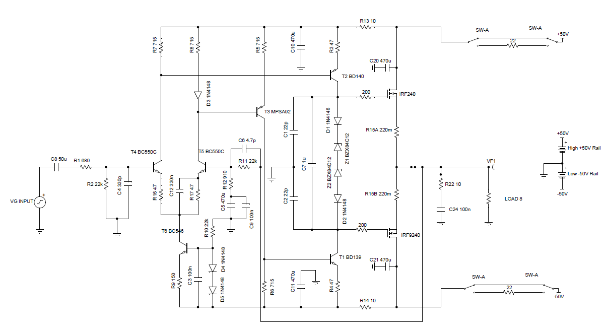
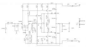
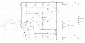
Thanks to egra for posting his TINA simulation. Once I had the sim, which has excellent performance btw, I had to answer a nagging question: what happens if you swap out the nice Hitachi's for some dirt cheap hex-FETs like the venerable IRFP240 and IRFP9240? I put those in and sure enough, the distortion above 3kHz started to degrade badly. I recall that often when IRFP's are used in Pass amps, there are some "emitter" (or shall I say drain/source) resistors. So I added a 0.22ohm resistor between the output pin and common point. This really cleaned up the distortion and this amp appears to make clean 20kHz squarewaves and have pretty low distortion - even when driven at high power. The hex-FETs can take higher current and voltage too so I boosted the rails to 50v. Assuming the other transistors and caps can all take it - does this make sense that it can work? Here is the schematic:
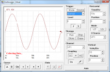
Here is the scope with 20kHz 1.41v sine wave excitation:

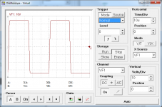
Here us the scope with square wave at 20kHz:

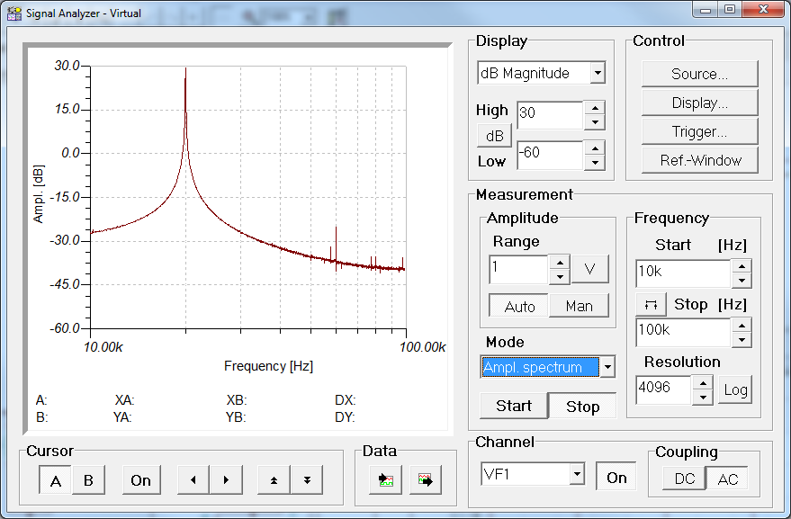
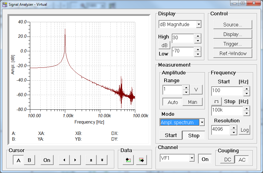
Here is the spectrum analyzer output for 20kHz excitation:
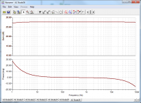
Here is the frequency response and phase plot:

Here is the requisite spectrum at 1kHz excitation:
Let me know if I have done something totally wrong. But if this is right, it means we can use plentiful $2 hex-FETs. Oh, and the 50v rails now mean that this is a 250w class amp?
Thanks to egra for posting his TINA simulation. Once I had the sim, which has excellent performance btw, I had to answer a nagging question: what happens if you swap out the nice Hitachi's for some dirt cheap hex-FETs like the venerable IRFP240 and IRFP9240? I put those in and sure enough, the distortion above 3kHz started to degrade badly. I recall that often when IRFP's are used in Pass amps, there are some "emitter" (or shall I say drain/source) resistors. So I added a 0.22ohm resistor between the output pin and common point. This really cleaned up the distortion and this amp appears to make clean 20kHz squarewaves and have pretty low distortion - even when driven at high power. The hex-FETs can take higher current and voltage too so I boosted the rails to 50v. Assuming the other transistors and caps can all take it - does this make sense that it can work? Here is the schematic:
Here is the scope with 20kHz 1.41v sine wave excitation:
Here us the scope with square wave at 20kHz:
Here is the spectrum analyzer output for 20kHz excitation:
Here is the frequency response and phase plot:
Here is the requisite spectrum at 1kHz excitation:
Let me know if I have done something totally wrong. But if this is right, it means we can use plentiful $2 hex-FETs. Oh, and the 50v rails now mean that this is a 250w class amp?
Attachments
-
 FX8-Egra-hexFET-Mod-Schematic.png58.1 KB · Views: 1,394
 -
 FX8-Egra-hexFET-Mod-O-scope-sine.png63.2 KB · Views: 1,379
 -
 FX8-Egra-hexFET-Mod-O-Scope.png62.8 KB · Views: 1,369
 -
 FX8-Egra-hexFET-Mod-Spectrum-Analyzer.png79 KB · Views: 1,366
 -
 FX8-Egra-hexFET-Mod-Bode.png65 KB · Views: 1,364
 -
 FX8-Egra-hexFET-Mod-Spectrum-Analyzer-1khz.png83.1 KB · Views: 1,358
Last edited:
HEXFETs will require a Vbe multiplier for thermal compensation, since the negative temperature coefficient does not come into play until the device has about 10 amps through it (at least for the IRFP240). The exact values around the Vbe multiplier (also known as a bias servo) are critical to ensure that the thermal performance is matched as closely as possible.
Using HEXFETs in High Fidelity Audio
Using HEXFETs in High Fidelity Audio
Xrk, connect the protection Zeners to the output rail.
Add drivers between VAS and outputs.
Sorry, I am new at this. Would you mind marking up my schematic?
Thanks.
Thanks to egra for posting his TINA simulation. Once I had the sim, which has excellent performance btw, I had to answer a nagging question: what happens if you swap out the nice Hitachi's for some dirt cheap hex-FETs like the venerable IRFP240 and IRFP9240?
If you want a simple amplifier using HEXFETS, take a look at Apex A9. You can also use its schematic as a basis for modifying AX11/FX8 to use HEXFETS. Just copy the OPS part (VBE multiplier, drivers and output fets) from the A9.
- Home
- Amplifiers
- Solid State
- 100W Ultimate Fidelity Amplifier